Pinpoint Test A: Transaxle Control Solenoids
Pinpoint Tests - OSC Equipped Vehicle

Any time an electrical connector or solenoid body is disconnected, inspect the connector for terminal condition, corrosion and contamination. Also inspect the connector seal for damage. Clean, repair or install new components as required.
Shift Solenoid Pre-Diagnosis
Use the following shift solenoid operation information when carrying out Pinpoint Test A.
Solenoid Operation Chart
Solenoid Operation Chart:

a Solenoid state will change if vehicle is moving forward with the selector lever in the NEUTRAL position.
CB = Clutch brake
NC = Normally closed
NH = Normally high
NL = Normally low
Shift Solenoid Failure Mode Chart "Failed ON" or "Failed OFF"
Failed ON/OFF due to PCM and/or vehicle wiring concerns and/or solenoid electrically, mechanically or hydraulically stuck on/off.
Shift Solenoid A (SSA)

Shift Solenoid B (SSB)

a Reverse is available if the solenoid circuit failed causing transaxle solenoid power control solenoid to remove voltage to all solenoids.
Shift Solenoid C (SSC)

Shift Solenoid D (SSD)

a Reverse is available if the solenoid circuit failed causing transaxle solenoid power control solenoid to remove voltage to all solenoids.
b No engine braking.
Shift Solenoid E (SSE)

a No engine braking.
Pinpoint Tests
PINPOINT TEST A: TRANSAXLE CONTROL SOLENOIDS
NOTE: Refer to the transaxle connector illustrations and solenoid body leadframe internal wiring diagram Transaxle Connector Layouts Transaxle Connector Layouts.
-------------------------------------------------
A1 ELECTRONIC DIAGNOSTICS
- Check to make sure the transaxle harness connector is fully seated, terminals are engaged in connector and in good condition before proceeding.
- Connect the scan tool.
- Carry out the Key ON Engine OFF (KOEO) until continuous DTCs have been displayed.
- Enter the Output Test Mode.
- Select the mode ALL ON. Push START to turn outputs ON. Push STOP to turn outputs OFF.
- Does vehicle enter Output Test Mode?
Yes
GO to A2 .
No
PRESS START. If vehicle does not enter Output Test Mode, REFER to Computers and Control Systems Information.
-------------------------------------------------
A2 CHECK THE SOLENOID CIRCUIT FOR AN OPEN
- Ignition OFF.
- Disconnect: Transaxle Vehicle Harness C1520a.
- Use a mirror to inspect both ends of the connector for damage or pushed-out pins, corrosion, loose wires and missing or damaged seals.
- Disconnect: PCM Transaxle Harness C175T .
- Use a mirror to inspect both ends of the connector for damage or pushed out pins, corrosion, loose wires and missing or damaged seals.
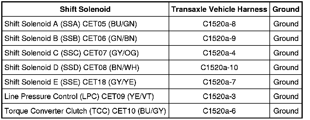
- Measure the resistance of the suspect solenoid circuit between the PCM transaxle harness C175T and transaxle vehicle harness C1520a using the following chart.

- Is the resistance less than 5 ohms?
Yes
GO to A3.
No
REPAIR the circuit(s) for an open. RECONNECT all components. TEST the system for normal operation.
-------------------------------------------------
A3 CHECK THE SOLENOID CIRCUIT FOR A SHORT TO GROUND
- Measure the resistance between the transaxle vehicle harness C1520a, harness side and ground using the following chart.
- Is the resistance greater than 10,000 ohms?
Yes
GO to A4.
No
REPAIR the circuit(s) for a short to ground. RECONNECT all components. TEST the system for normal operation.
-------------------------------------------------
A4 CHECK THE SOLENOID CIRCUIT FOR A SHORT TO POWER
- Measure the voltage between the transaxle vehicle harness electrical C1520a, harness side and ground using the following chart.

- Is any voltage present?
Yes
REPAIR the circuit(s) for a short to power. RECONNECT all components. TEST the system for normal operation.
No
GO to A5.
-------------------------------------------------
A5 CHECK THE RESISTANCE OF THE SOLENOID FIELD CIRCUIT
- Measure the resistance between the transaxle solenoid body leadframe main electrical connector C1520a pin 5, component side and the suspect solenoid pin, component side and compare the value to the specifications in the table below.

Solenoid Resistance Values: SHIFT SOLENOID A (SSA), SHIFT SOLENOID B (SSB), SHIFT SOLENOID C (SSC), SHIFT SOLENOID D (SSD), TORQUE CONVERTER CLUTCH (TCC) and LINE PRESSURE CONTROL (LPC)

Solenoid Resistance Values: SHIFT SOLENOID E (SSE) (ON/OFF)

- Is the resistance within specifications?
Yes
INSTALL a new PCM. REFER to Computers and Control Systems. RECONNECT all components. TEST the system for normal operation.
No
REMOVE the main control cover. REFER to Main Control Cover Service and Repair. INSPECT the solenoid body for foreign material such as metal shavings on the exposed metal contacts or other components.
CLEAR the solenoid body and RECHECK the resistance values. If the resistance values are still out of specification, GO to A6. INSTALL a new solenoid(s). REFER to Solenoids Solenoids.
RECONNECT all components. TEST the system for normal operation.
-------------------------------------------------
A6 CHECK THE SOLENOID BODY LEADFRAME FOR AN OPEN
- Remove the solenoid body leadframe. Refer to Solenoid Body Leadframe Solenoid Body Leadframe.
- Measure the resistance between the solenoid body leadframe main electrical connector C1520a, component side and the corresponding solenoid pins using the following chart.


- Is the resistance less than 5 ohms?
Yes
INSTALL a new solenoid(s). REFER to Solenoids Solenoids. RECONNECT all components. TEST the system for normal operation.
No
INSTALL a new solenoid body leadframe. REFER to Solenoid Body Leadframe Solenoid Body Leadframe.
-------------------------------------------------