Power Supply/MFI Relay


CIRCUIT DIAGRAM
OPERATION
In this power supply circuit for ECU, power is supplied to both IG [ON] and ECU. The control relay supplies power to the fuel pump, injector, AFS, etc. in addition to ECU.
INSPECTION

Using Multi-use tester
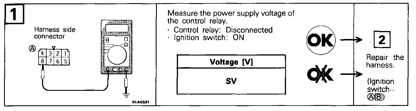
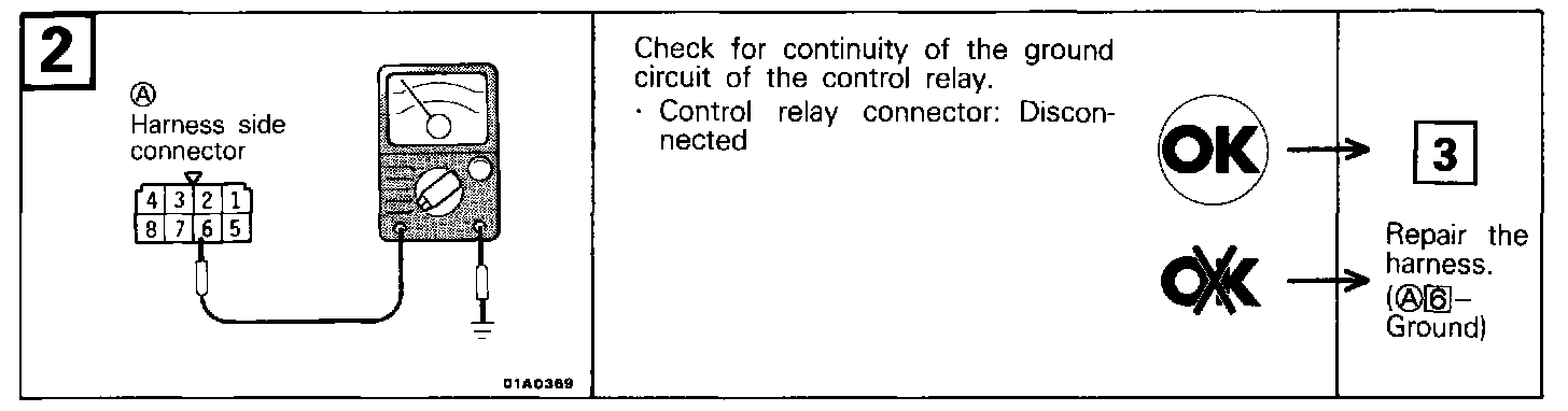
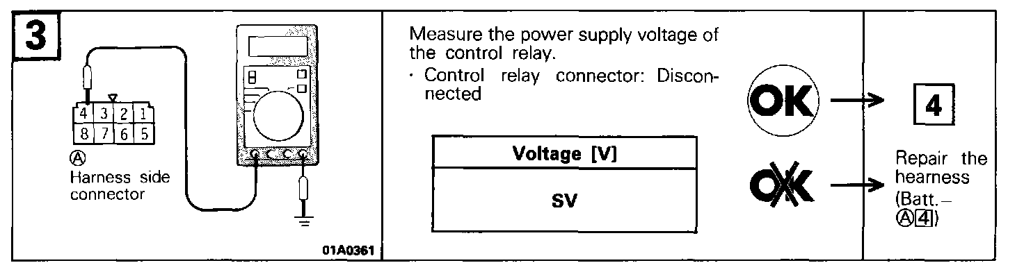
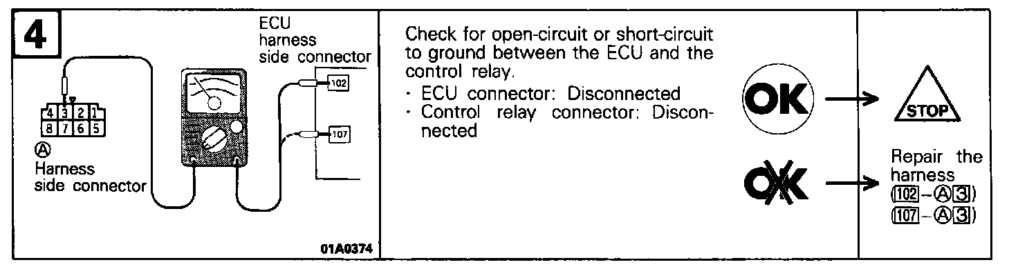
HARNESS INSPECTION
CONTROL RELAY INSPECTION
(1) Remove the control relay.
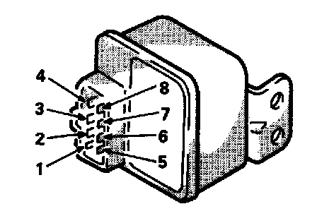
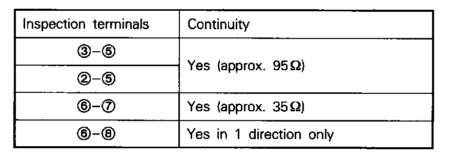
(2) Inspect the continuity between the control relay terminals.
(3) Use jumper wires and connect control relay terminal (7) to the battery (+) terminal and terminal (6) to the battery (-) terminal.
CAUTION Be very careful when connecting the jumper wires because the relay will be damaged if a mistake is made with the contact terminals.
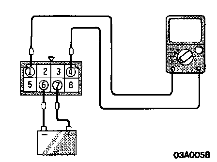
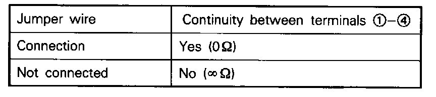
(4) With the battery (-) terminal jumper wire connected and disconnected, check the continuity between control relay terminals (1)-(4).
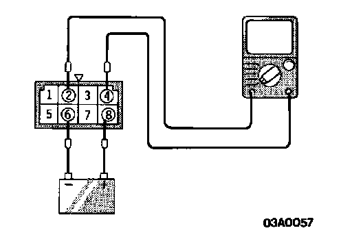
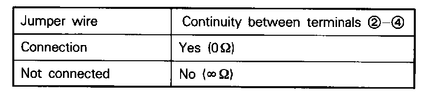
(5) Use jumper wires to connect control relay terminal (8) to the battery (+) terminal and terminal (6) to the battery (-) terminal.
(6) With the battery (-) terminal jumper wire connected and disconnected, check the continuity between control relay terminals (2)-(4).
(7) Replace the control relay if faulty.