Power Mirror Switch: Testing and Inspection
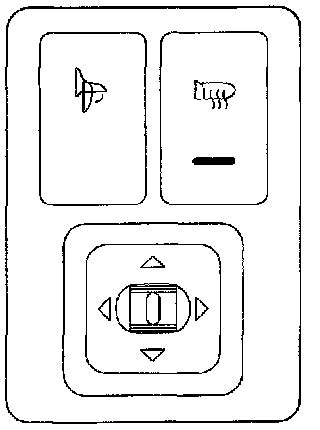
The door mirror switch is made up of the control switch that controls the vertical and horizontal movement of both mirrors, the folding switch, and the defogger switch.
The control switch consists of six switches, two of which are used to select a mirror on either the left or the right side, and the remaining four switches control vertical or horizontal mirror movement.
The folding switch contains two switches, and their contacts are changed over each time these switches are depressed. The direction of the current flow to the motor in the mirror is controlled to perform the folding and returning action of the mirror.
When depressing the defogger switch, the defogger indicator lights up to inform the driver that the mirror built-in heater is operating.
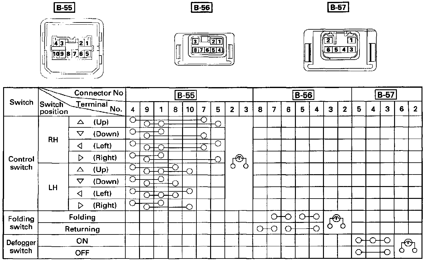
Check to see if there is any continuity between the connector terminals while operating the door mirror switch.
Repair or replace the switch when the result of inspection is found abnormal.
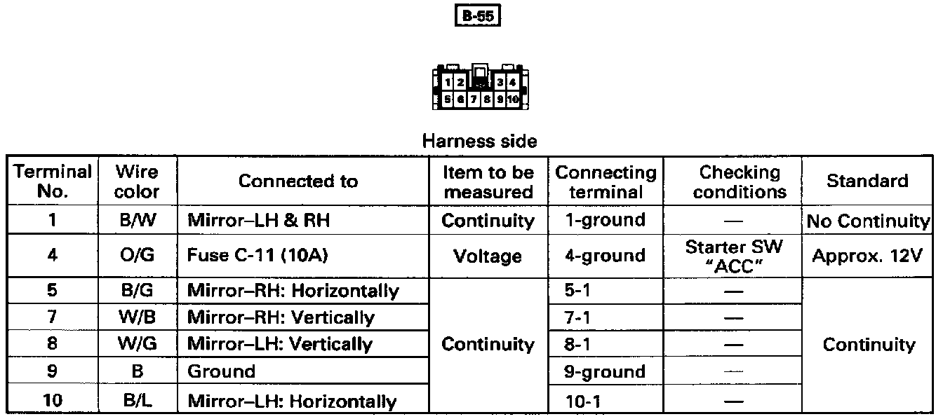
Circuit inspection of the control switch
Remove the connector [B-55] of the control switch and check the voltage and continuity of the harness side connector of the vehicle.
^ When there is no continuity at the terminal No.5, 7, 8, 10, it is considered that the circuit with terminal NO.1 (B/W) is defective.
^ When there is no continuity at either one of the circuit No.5, 7, 8, or 10, the motor in the mirror of the circuit or the circuit itself is defective.
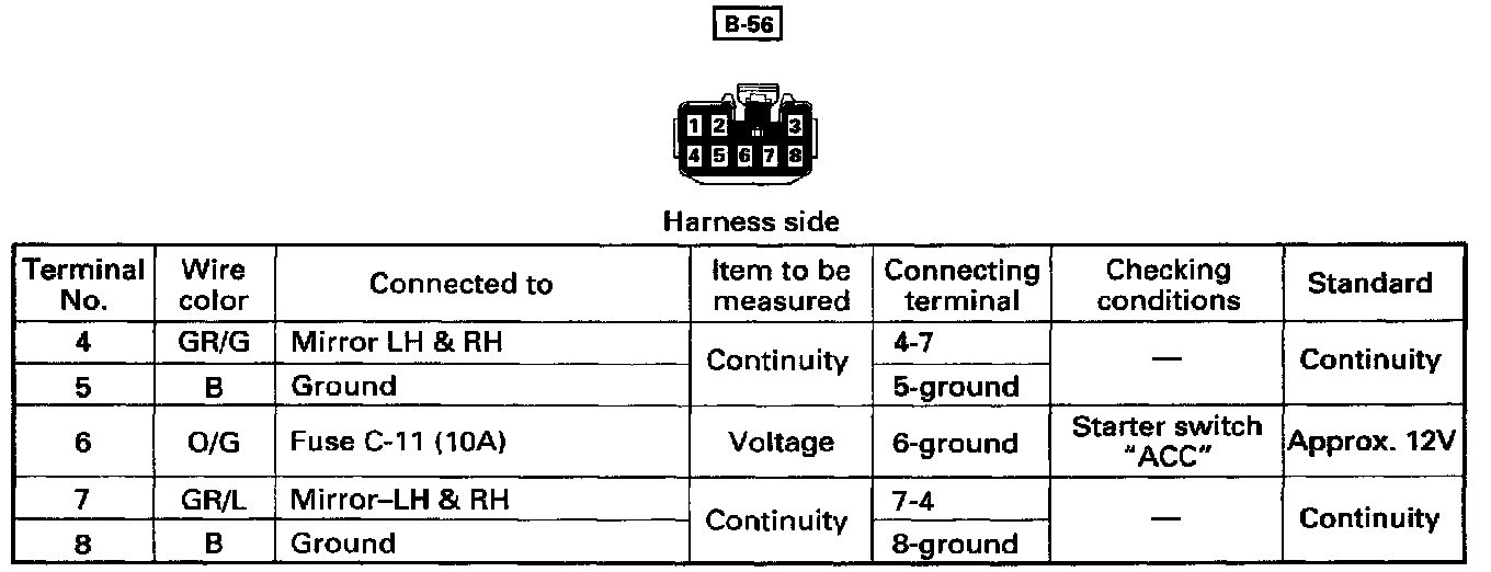
Circuit inspection of the folding switch
Remove the connector [B-56] of the folding switch and check the voltage and continuity of the harness side connector of the vehicle.
^ When there is no continuity at the terminal No. 4 and 7, the motor in the mirror of the circuit or the circuit itself is defective.
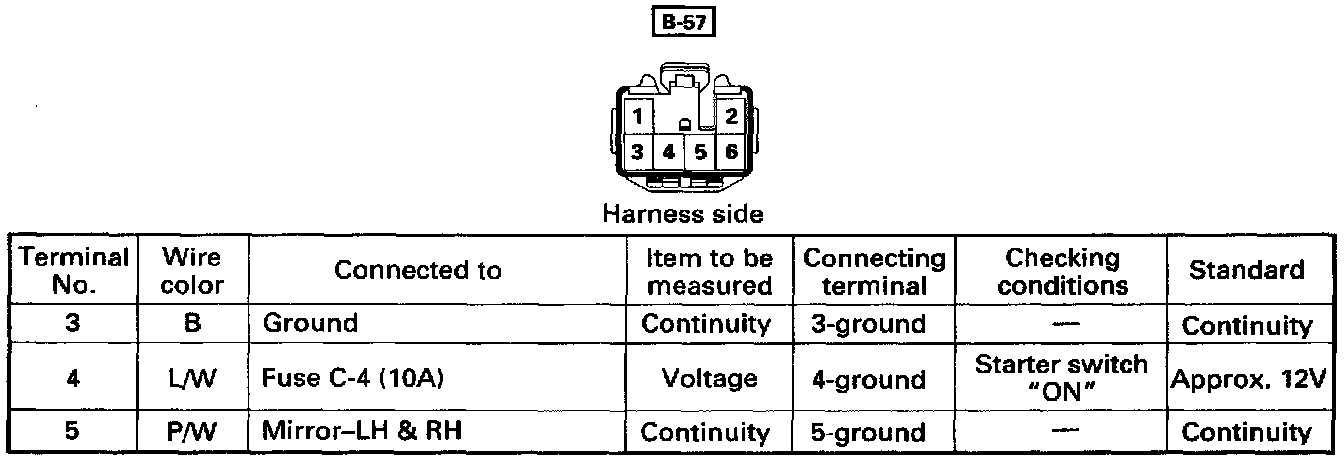
Circuit inspection of the defogger switch
Remove the connector [B-57] of the defogger switch and check the voltage and continuity of the harness side connector of the vehicle.