Transmission Mode Switch: Service and Repair
REMOVALPreparation:
- Disconnect negative (-) battery cable.
- Place selector lever in neutral.
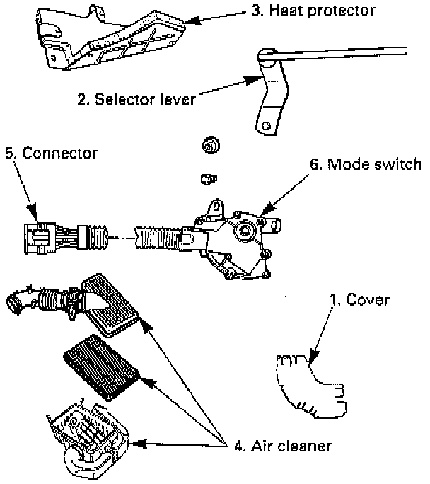
1. Mode switch cover.
2. Selector lever
- Disconnect selector lever from the mode switch.
3. Heat protector
- Remove heat protector from the converter housing.
4. Air cleaner assembly.
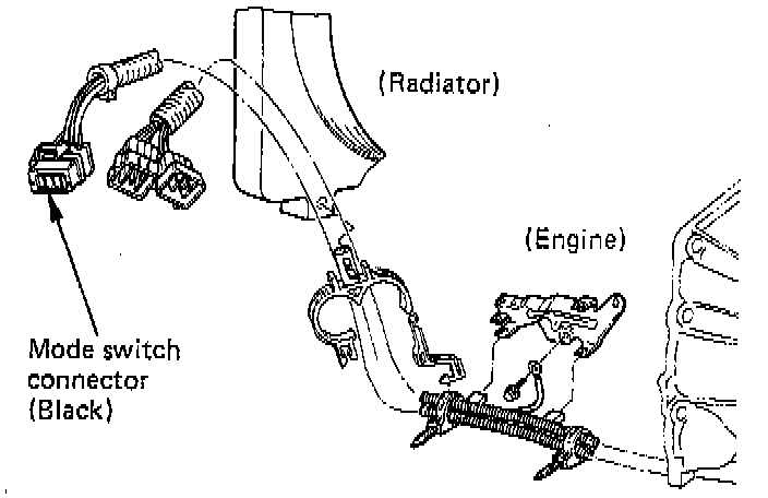
5. Harness connector Disconnect mode switch connector from the engine harness.
- Disconnect harness clip from the clip bracket of the engine.
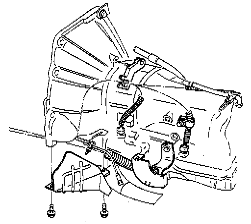
6. Mode switch.
- Remove two mode switch bolts.
INSTALLATION
To install, follow the removal steps in the reverse order, noting the following points:
1. Torque:
Mode switch bolt: 13 Nm (113 inch lbs.)
Heat protector bolt: 6 Nm (52 inch lbs.)
Selector lever nut: 23 Nm (17 ft.lbs.).
2. Mode switch setting procedure.
Perform either of the following adjustment procedures:
a. Procedure 1
1. Place selector lever in neutral.
2. Remove selector lever from the mode switch.
3. Remove the mode switch cover.
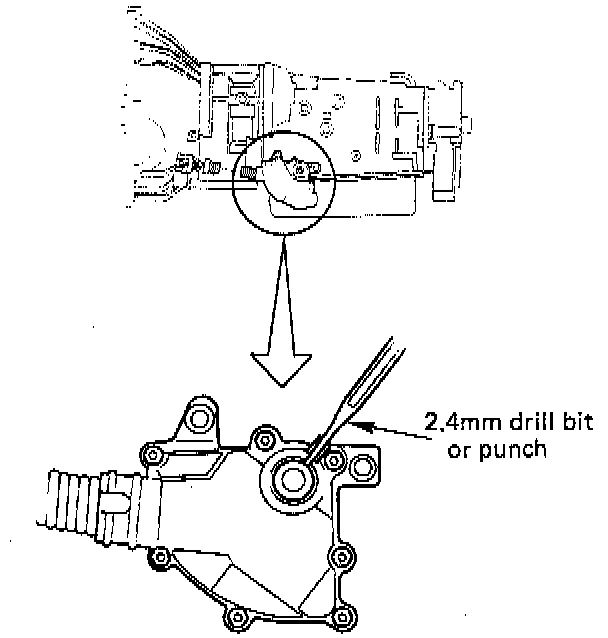
4. Loosen the two 10 mm screws.
5. Rotate the mode switch until the slot in the mode switch housing aligns with the selector shaft bushing, and insert a 3/32 inch (2.4 mm) drill bit or punch into the slot.
6. Tighten the screws to 13 Nm (113 inch lbs.).
7. After completing adjustment, snap the mode switch cover into place.
8. Install the selector lever.
b. Procedure 2
1. Place selector lever in neutral.
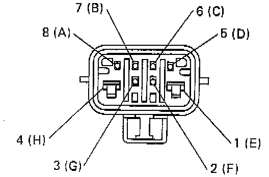
2. Disconnect mode switch connector from vehicle harness.
3. Connect multimeter (resistance mode) to terminals 1(E) and 4(H) on mode switch connector.
4. Loosen two mounting screws.
5. Rotate mode switch slightly in both directions to determine the range (approximately 5°) of electrical contact.
6. Position mode switch in middle of contact range.
7. Tighten two mounting screws.
8. Remove multimeter and reconnect harness.