Fuel Injectors, Checking
Fuel Injectors, Checking
The following procedure is used to diagnose N30, N31, N32, N33, N83, N84
Special tools, testers and auxiliary items required
- Multimeter.
- Diode test lamp (12 V).
- Wiring diagram.
Test requirements
- The Fuel Injectors N30, N31, N32, N33,N83,N84 fuses OK.
- The Engine Speed (RPM) Sensor G28 OK.
- Battery voltage at least 12.5 volts.
- All electrical consumers such as, lights and rear window defroster, switched off.
- Vehicles with automatic transmission, shift selector lever into position "P" or "N".
- A/C switched off.
- Ground (GND) connections between engine/transmission/chassis OK.
- Ignition switched off.
Procedure
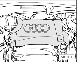
- Remove the rear engine cover - arrows -.
Right bank
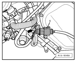
- Disconnect the 6 pin electrical harness connector - 1 - for Fuel Injectors N30, N31, N32 from the right rear of the engine.
Left bank
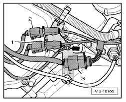
- Disconnect the 14 pin electrical harness connector - 3 - for Fuel Injectors N33, N83, N84 from the left rear of the engine.
Checking internal resistance
- Using a Multimeter, check the Fuel Injectors for resistance.
Right bank
Fuel Injector 6 pin electrical harness connector terminal
N30 Cyl. 1 1 to 2
N31 Cyl. 2 3 to 4
N32 Cyl. 3 5 to 6
Left bank
Fuel Injector 14 pin electrical harness connector terminal
N33 Cyl. 4 5 to 6
N83 Cyl. 5 7 to 8
N84 Cyl. 6 9 to 10
Specified value: 12 to 13 Ohms (at room temperature).
NOTE: With an engine at operating temperature, the resistance of the fuel injectors increases by approx. 4 to 6 Ohms.
If any of the specified values are not obtained:
- Replace the malfunctioning Fuel Injector.
If the specified values are obtained:
Checking activation
- Connect a diode test lamp (12 V) to the electrical harness connector terminals of the Fuel Injector to be tested.
Right bank
Fuel Injector 6 pin electrical harness connector terminal
N30 Cyl. 1 1 to 2
N31 Cyl. 2 3 to 4
N32 Cyl. 3 5 to 6
Left bank
- Operate the starter briefly.
NOTE: Voltage testers do not go out completely during low current pick-up between activations by the ECM, but rather continue to glow a little and then get slightly brighter during activation.
The LED must light up.
- Switch the ignition off.
If the LED does not light up:
Checking wiring
If the manufacturers test box is being used. Perform the following step.
- Install the test box.
If the manufacturers test box is not being used. Perform the following step.
- Remove the Engine Control Module (ECM) J623.
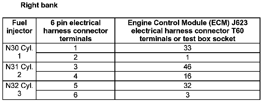
- Using a Multimeter, check the Fuel Injector electrical harness connector terminals to the Engine Control Module (ECM) J623 electrical harness connector T60 terminals for an open circuit.
Right bank
Left bank
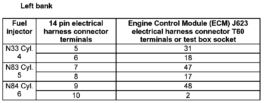
Specified value: 1.5 Ohms Max.
If any of the specified values are not obtained:
- Check the wiring for a short circuit to each other, Battery (+), and Ground (GND).
- Check the electrical harness connector for damage, corrosion, lose or broken terminals.
- If necessary, repair the faulty wiring connection.
If no malfunction is detected in the wiring:
- Replace the Engine Control Module (ECM) J623.

- Install the rear engine cover - arrows -.
Final procedures
After the repair work, the following work steps must be performed in the following sequence:
1. Check the DTC memory.
2. If necessary, erase the DTC memory.
3. If the DTC memory was erased, generate readiness code.
- End of diagnosis.