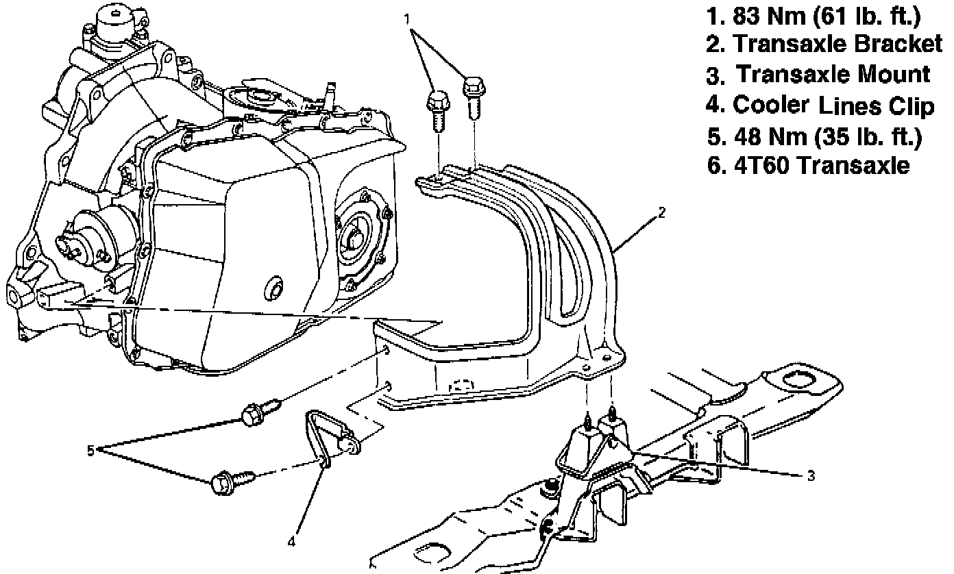
Transaxle Bracket
TRANSAXLE BRACKET 4T60 (440-T4)Transaxle Mount Bracket - Hydra-Matic 4T60:
TOOLS REQUIRED:
^ J 28467-A Engine Support Fixture
^ J 28467-90 Engine Support Fixture Adapter
^ J 36462 Support Adapter Leg
REMOVE OR DISCONNECT
1. Air cleaner assembly.
2. Negative battery cable.
3. Install J 28467-A, J 28467-90 and J 36462.
4. Bolts at top of transaxle mount bracket.
5. Raise vehicle and suitably support.
6. Left front tire and wheel assembly.
7. Left lower engine splash shield.
CAUTION: Failure to disconnect the intermediate shaft from the rack and pinion stub shaft can result in damage to the steering gear and/or intermediate shaft. This damage may cause loss of steering control which could result in personal injury.
8. Pinch bolt at intermediate steering shaft.
9. Support right and left sides of frame with jackstands.
10. Nuts attaching bracket to mount.
11. Left frame to body bolts.
12. Adjust jackstand to lower left side of frame.
13. Bolts holding engine wiring harness to transaxle case.
14. Transaxle oil cooler lines at transaxle.
15. Bolts attaching bracket to transaxle.
16. Bracket.
INSTALL OR CONNECT
1. Bracket.
2. Side bolts attaching bracket to transaxle.
TIGHTEN
^ Front bolts/screws to 48 Nm (35 lb. ft.).
3. Transaxle oil cooler lines at transaxle.
4. Bolts holding engine wiring harness to transaxle case.
5. Raise left side of frame and install new frame to body bolts.
6. Nuts attaching bracket to mount.
TIGHTEN
^ Nuts to 43 Nm (32 lb. ft.).
CAUTION: When installing the intermediate shaft make sure the shaft is seated prior to pinch bolt installation. If the pinch bolt is inserted into the coupling before shaft installation, the two mating shafts may disengage.
7. Pinch bolt at intermediate steering shaft.
8. Splash shield.
9. Tire and wheel assembly.
10. Lower vehicle.
11. Bolts at top of transaxle mount bracket.
TIGHTEN
^ Bolts to 83 Nm (61 lb. ft.).
12. Remove J 28467-A, J 28467-90 and J 36462.
13. Negative battery cable.
14. Air cleaner assembly.