Installation Procedure (Left)
Important:Always install a new fuel pump strainer on the left fuel sender assembly before reinstalling the left fuel sender assembly. A fuel pump strainer that has been exposed to fuel will not unfold in the fuel tank and may block full travel of the float arm.
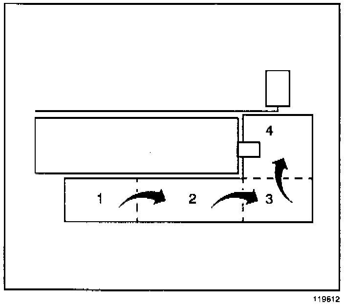
1. Install a new fuel pump strainer in the same position as noted during disassembly. Push on the outer edge of the strainer ferrule until the strainer is fully seated.
Caution:
In order to reduce the risk of fire and personal In Jury that may result from a fuel leak, always replace the fuel sender gasket and the fuel sender attaching bolts when reinstalling the fuel sender assembly.
2. Install a new fuel sender gasket on the fuel sender.
3. Fold the strainer three times so that the amount of space occupied by the strainer is about equivalent to the diameter of the fuel sender reservoir.
3.1. Fold the long side of the strainer over (1 over 2).
3.2. Fold 3 over 4 and hold the strainer in the folded position.
4. Insert the fuel sender through the fuel tank opening.
5. Release the strainer once the strainer is in the fuel tank. The strainer will spring back to its full position.
6. Continue inserting the fuel sender through the fuel tank opening. It may be necessary to rotate the fuel sender in order to facilitate the installation.
6.1. Look through the fuel tank opening to ensure that the long side of the strainer is visible.
6.2. If the strainer is not visible, rotate the fuel sender clockwise and counterclockwise about 90 degrees. Rotating the fuel sender will free up the strainer. The strainer should become visible at the tank opening.
Important:
Do not bend or twist the float arm.
7. Insert the float and the float arm into the fuel tank opening.
8. Install the float arm on the fuel sender.
9. Install the float arm retaining clip.
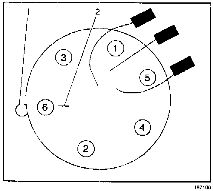
10. Align the fuel sender gasket tab (1) with the fuel sender cover mark (2).
11. Align the fuel sender cover mark (2) with the fuel tank mark.
Notice:
Refer to the Fastener Notice in Cautions and Notices.
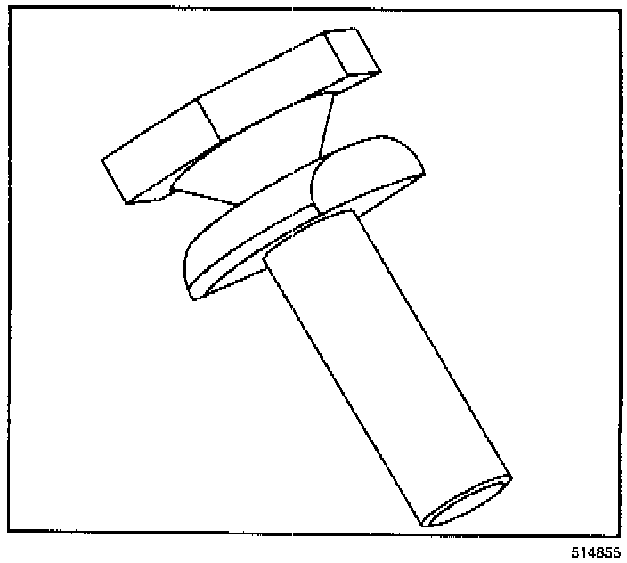
12. Hand tighten the new "break-away head" fuel sender attaching bolts until finger tight.
Important:
The upper hex head portion of the fuel sender attaching bolts is designed to shear off of the lower section of the bolt when the proper torque is reached. Do not tighten the bolts after the bolt heads have sheared off. A torque wrench or other special tool(s) are not required. Do not use thread locking or other types of sealers or lubricants when installing these bolts and gasket.
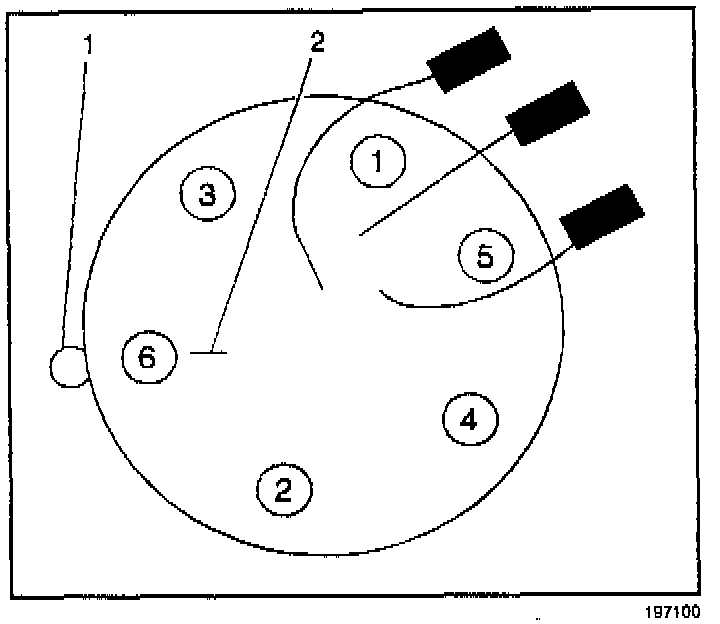
13. Tighten the new "break-away head" fuel sender assembly attaching bolts in sequence until the upper hex head portion of the bolts shear off of the lower section.
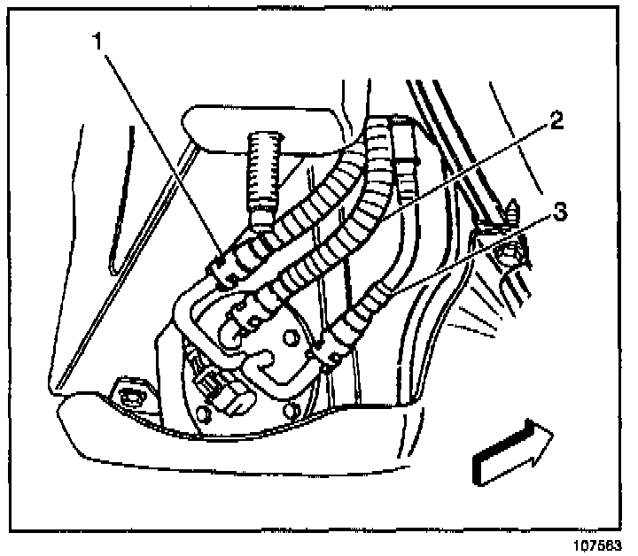
14. Connect the fuel sender fuel feed pipe (1) (jet pump to left tank), the fuel return rear pipe (2), and the fuel feed rear pipe (3). Refer to Servicing Quick Connect Fitting (Metal Collar) or Servicing Quick Connect Fitting (Plastic Collar).
15. Connect the fuel sender electrical connector.
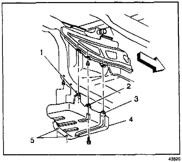
16. Install the fuel tank strap/shield.
17. Install the fuel tank strap/shield bolts.
17.1. Install the net hole bolt (3).
17.2. Install the slot location bolt (1).
17.3. Install the remaining bolts (2 and 5).
Tighten
Tighten the fuel tank strap/shield bolts to
25.5 N.m (19 lb ft).
18. Install the rear wheel and tire assembly. Refer to Wheel Removal in Tires and Wheels.
19. Lower the vehicle.
20. Refill the fuel system.
21. Install the fuel filler cap.
22. Connect the negative battery cable.
23. Inspect for leaks.
23.1. Turn the ignition switch ON for 2 seconds.
23.2. Turn the ignition switch OFF for 10 seconds.
23.3. Turn the ignition switch ON.
23.4. Check for fuel leaks.
24. Program the transmitters. Refer to Transmitter Programming/Synchronization in Keyless Entry.
25. Perform the idle learn procedure. Refer to PCM Idle Learn Procedure.