Installation Procedure
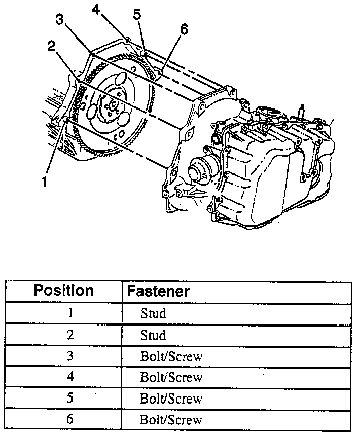
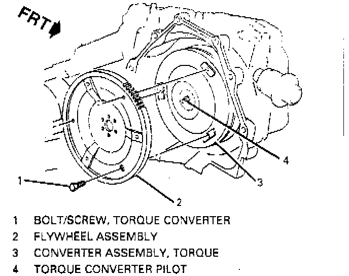
^ Tools Required:
- J 28467-500 Engine Support Fixture
- J 28467-6A Engine Support Fixture Lift Hook Bracket
- J 28467-7A Engine Support Fixture Lift Hook
- J 28467-8A Engine Support Fixture Swivel Lift Hook
- J 28467-34 Engine Support Fixture Lift Hook Wing Nut
- J 35944-A Oil Cooler and Line Flusher
INSTALL OR CONNECT
NOTICE: Always use the correct fastener in the proper location. When you replace a fastener, use ONLY the exact part number for that application. The manufacturer will call out those fasteners that require a replacement after removal. The manufacturer will also call out the fasteners that require thread lockers or thread sealant. UNLESS OTHERWISE SPECIFIED, do not use supplemental coatings (paints, greases, or other corrosion inhibitors) on threaded fasteners or fastener joint interlaces. Generally, such coatings adversely affect the fastener torque and the joint clamping force, and may damage the fastener. When you install fasteners, use the correct tightening sequence and specifications. Following these instructions can help you avoid damage to parts and systems.
1. Transaxle to frame on transaxle table.
2. Raise transaxle/frame assembly to vehicle.
3. Frame to body bolts/screws.
4. Lower transaxle to engine and engine to transaxle bolts/screws.
- Tighten bolts/screws to 75 Nm (55 ft. lbs.).
5. Transaxle brace.
6. Remove transaxle table.
7. Wiring harness connectors to transaxle.
- Vehicle speed sensor.
- Wheel speed sensors harness connectors.
8. Drive axles to transaxles.
9. Transaxle cooler lines and bracket to transaxle.
10. Torque converter bolts/screws.
- Tighten bolts/screws to 63 Nm (46 ft. lbs.).
11. Starter motor.
12. Converter cover bolts/screws and converter cover.
13. Lower ball joints to knuckles.
14. Mount to frame retaining nuts and washers.
15. Power steering cooler line clamps to frame.
16. Power steering gear to frame.
17. Power steering gear to frame retaining bolts/screws.
18. Power steering gear heat shield from power steering gear.
19. Both tie rod ends to steering knuckles.
20. Stabilizer shaft links from lower control arms.
21. Engine splash shields.
22. Front tires and wheels.
23. Fluid filler tube.
24. Remove vehicle support and lower vehicle.
25. Remove J 28467-500, J 28467-6A, J 28467-7A, J 28467-8A and J 28467-34.
26. Upper transaxle bolts/screws including wiring harness grounds.
- Tighten bolts/screw to 75 Nm (55 ft. lbs.).
27. Automatic transaxle range selector lever cable bracket with cable to transaxle.
28. Automatic transaxle range selector lever cable to transaxle range switch.
29. Wiring harness connectors to transaxle.
- Transaxle range switch.
- Solenoid harness connector.
30. Vacuum hose and pipe to vacuum modulator.
31. Air cleaner duct.
32. Fuel injector sight shield. Refer to Engine Cover Replacement Service and Repair.
33. Battery ground (negative) cable.
Adjust
- Toe-in, if required.
- Fluid level.
NOTICE: Do not overfill. Overfilling causes foaming and loss of fluid through the vent and may damage the automatic transaxle.
Inspect
- For proper completion of repairs.
- For proper fluid level.
- For fluid leaks.