Rocker Arm Assembly: Service and Repair
Valve Rocker Arm and Shaft Replacement
Tools Required
* EN-47610 (DW110-130-01) Crankshaft Pulley Holder
* EN-47611 (DW110-130-02) Crankshaft Pulley Installer/Remover
* EN-47612 (DW110-140) Timing Chain Cover Install Guide Pin
* EN-47613 (DW 110-150) Camshaft Sprocket Holder
* EN-47614 (DW 110-160) Rocker Arm Shaft Installer/Remover
Removal Procedure
Important:
Place the parts on a clean surface. Store the components in order so they can be reassembled in the same location and with the same mating surfaces as when removed.
1. Remove the engine assembly. Refer to Engine Replacement Removal and Replacement.
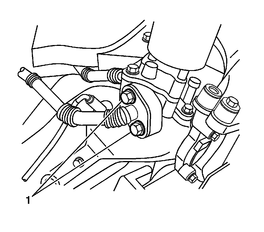
2. Remove the exhaust gas recirculation (EGR) pipe mounting bolts (1) and gasket from the EGR valve adapter.
3. Disconnect the positive crankcase ventilation (PCV) hose.
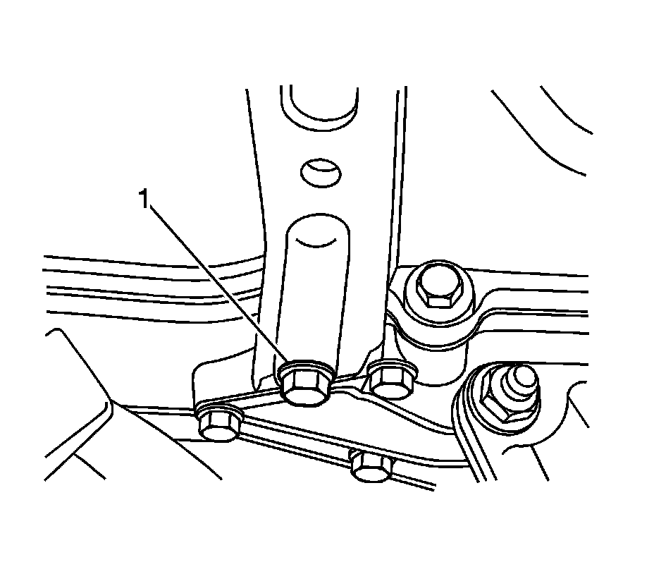
4. Remove the front support bracket retaining bolt (1) and the front support bracket.
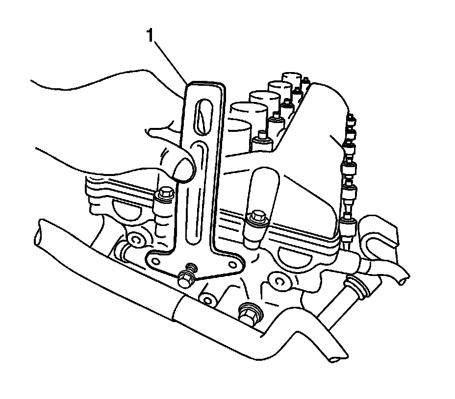
5. Remove the rear support bracket mounting bolts and the rear support bracket (1).
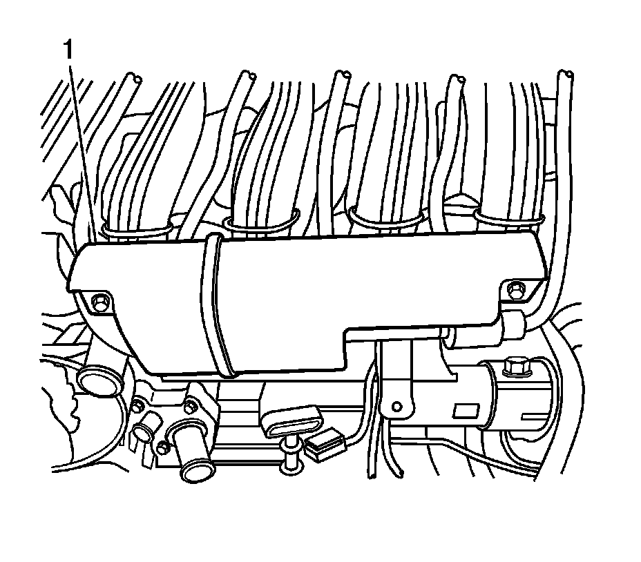
6. Remove the mounting bolts and the VIS vacuum tank (1).
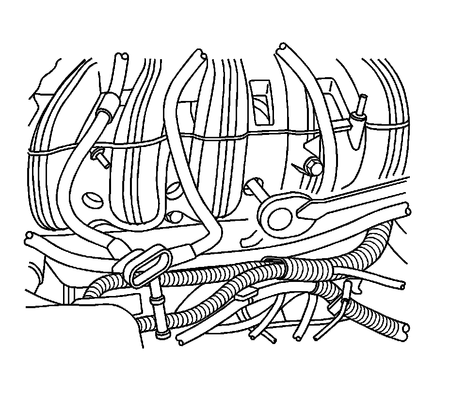
7. Remove the intake manifold retaining nuts and bolts.
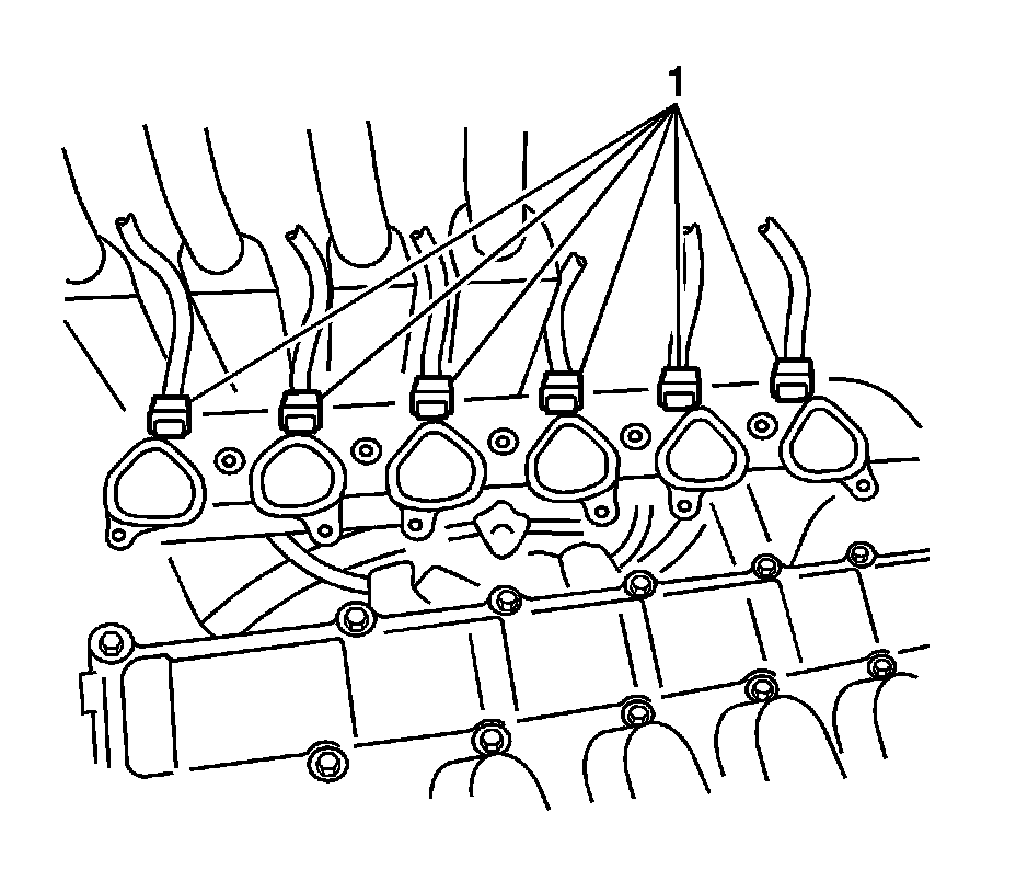
8. Separate the intake manifold from the engine assembly.
9. Disconnect the fuel injector connectors (1).
10. Remove the intake manifold.
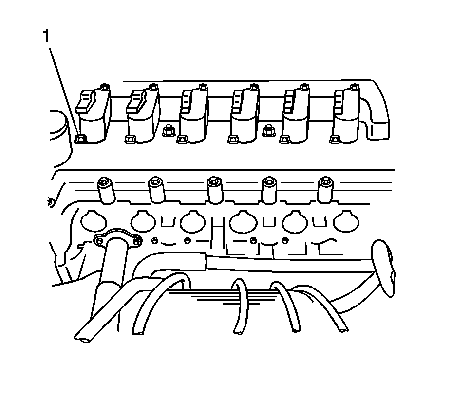
11. Remove the ignition coil retaining bolts (1), and the coils.
12. Remove the cylinder head cover mounting bolts, then remove the cover.
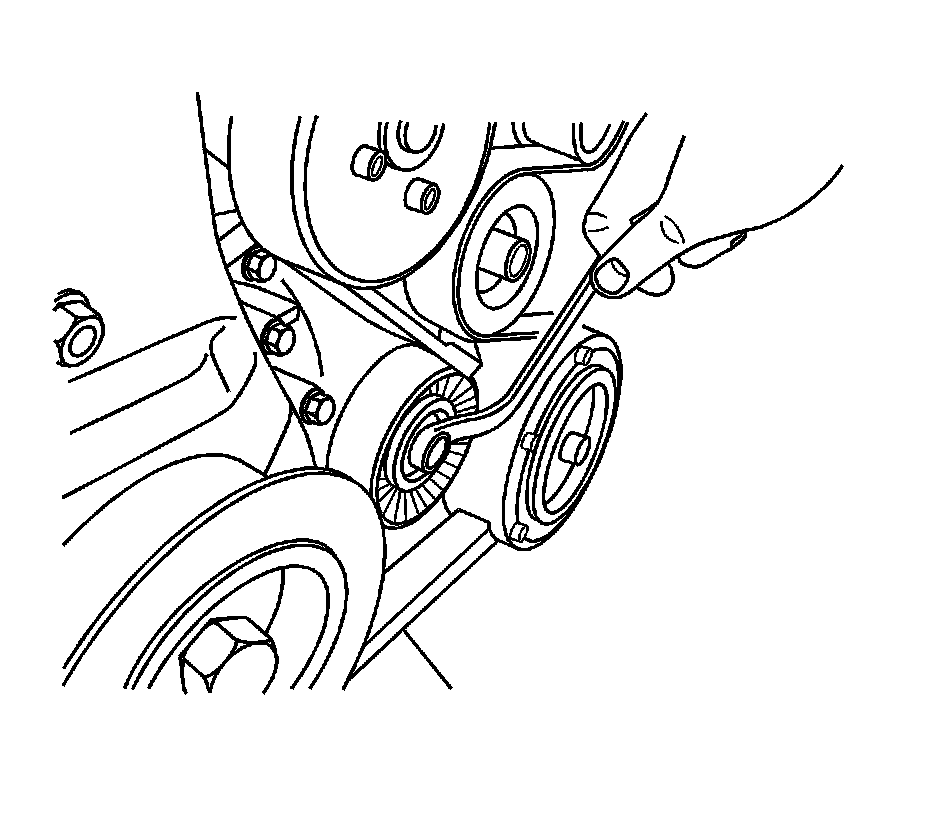
13. Remove the drive belt.
14. Install the EN-47610 (1), to the crankshaft pulley bolt.
15. Remove the crankshaft pulley bolt using EN-47611 (2).
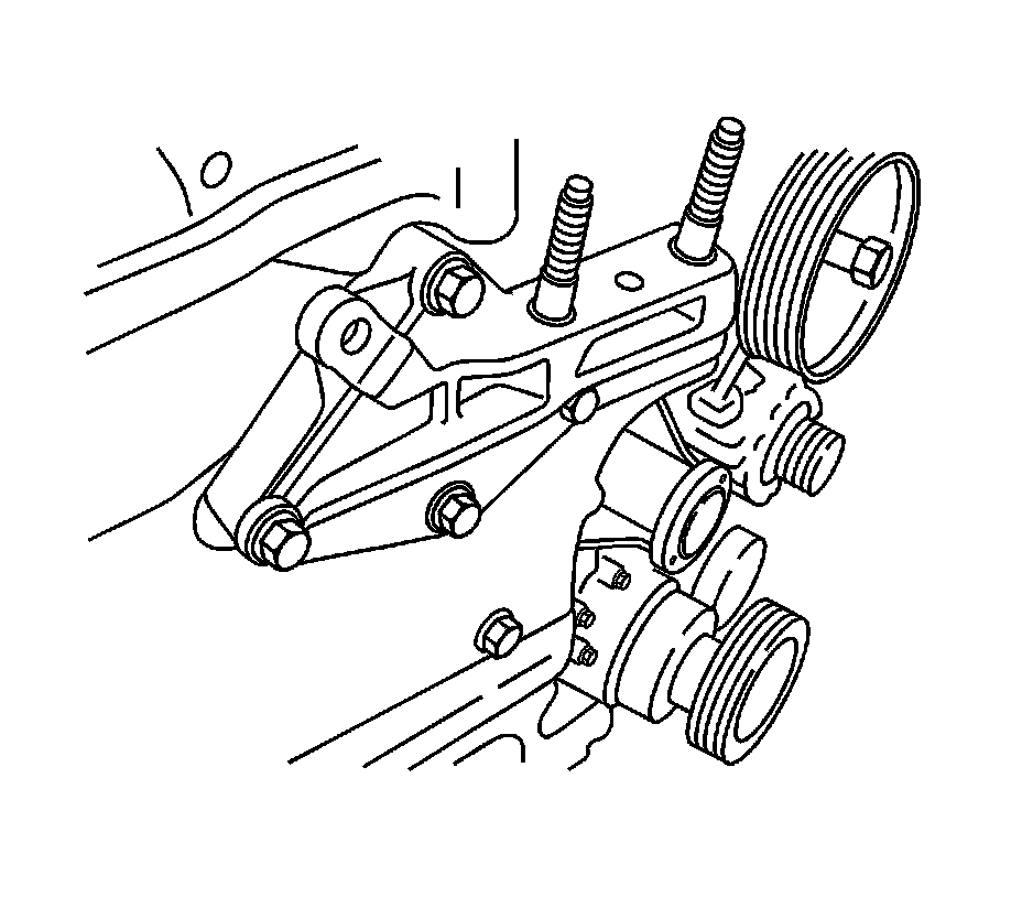
16. Remove the mounting bolts and the engine mount bracket support.
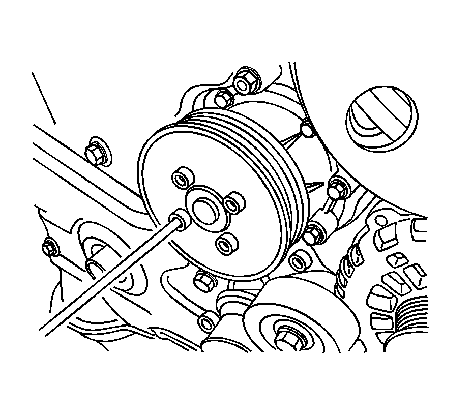
17. Remove the mounting bolts and the water pump pulley.
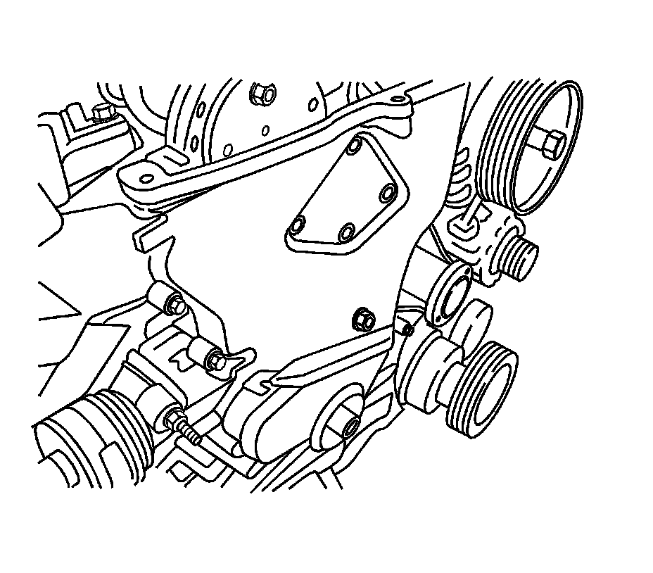
18. Remove the timing chain cover mounting bolts.
19. Remove the timing chain cover dowel rings.
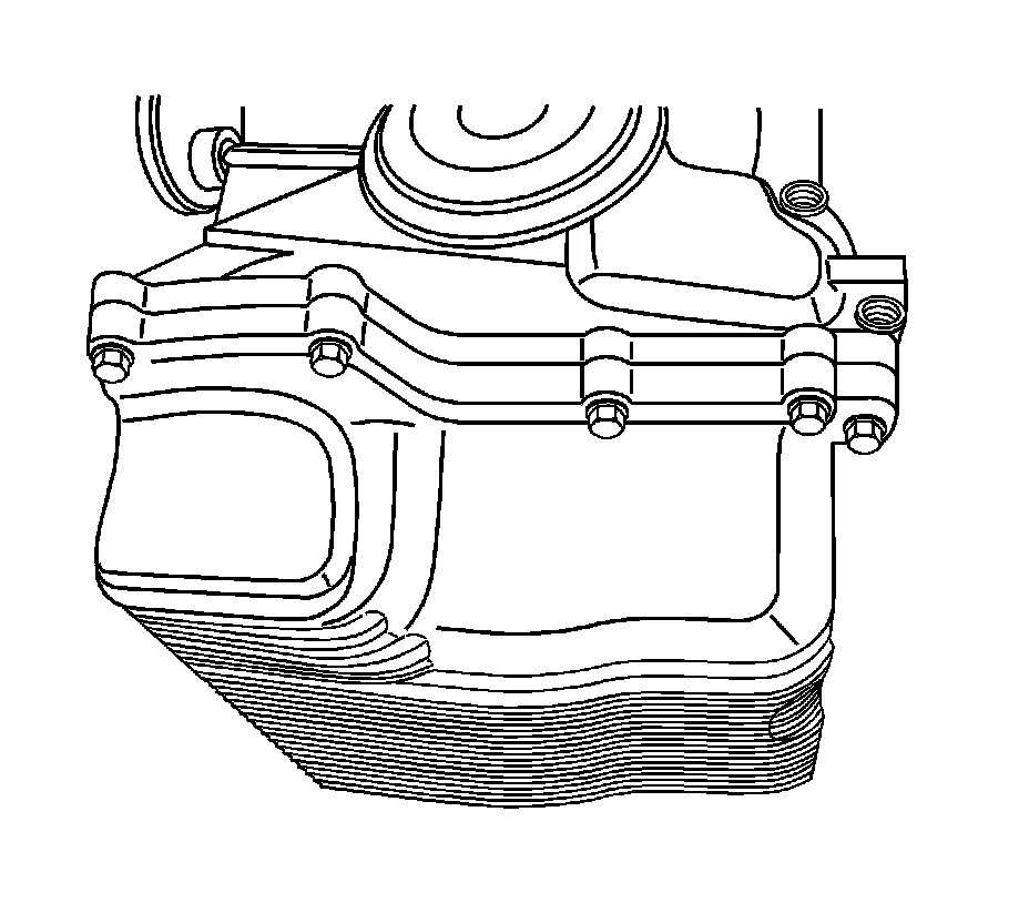
20. Remove the oil pan mounting bolts.
Important:
Before removing the tensioner, insert a pin into the tensioner access hole to keep the tensioner's position.
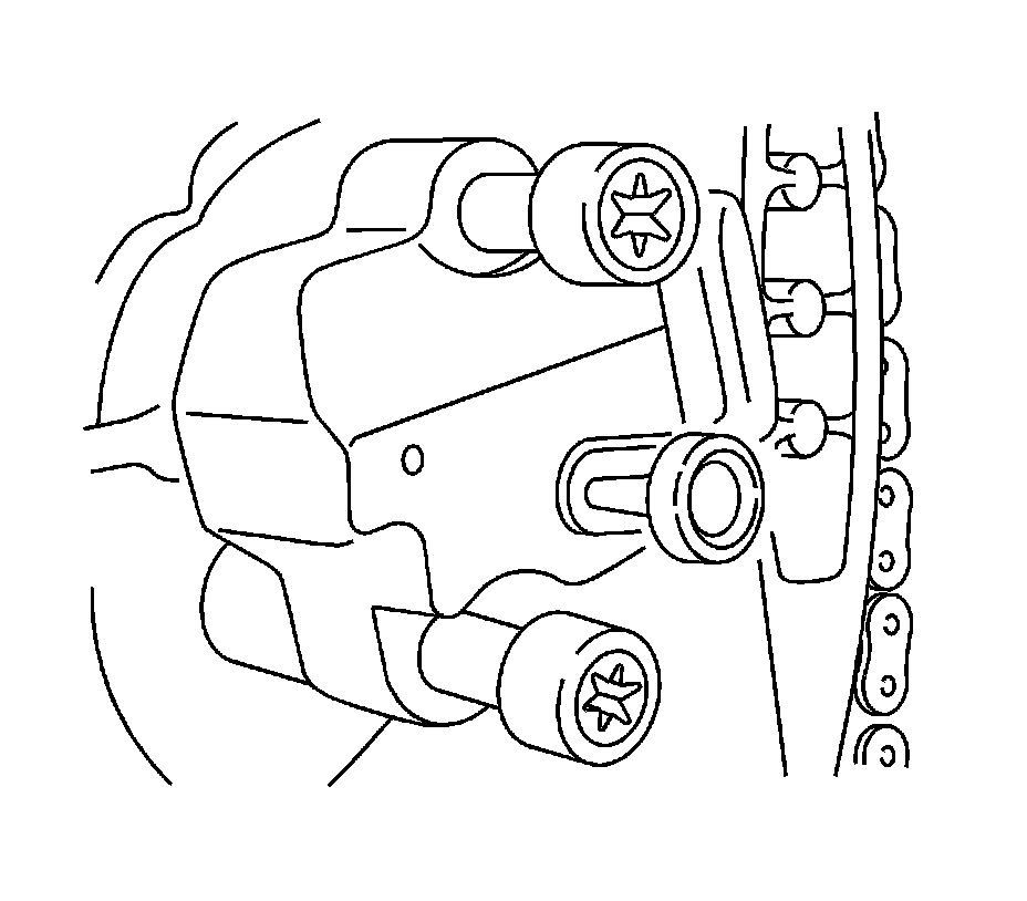
21. Remove the timing chain tensioner.
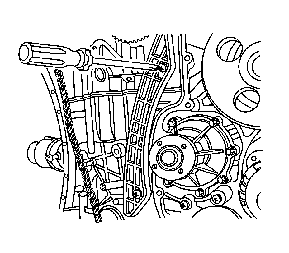
22. Remove the timing chain guide.
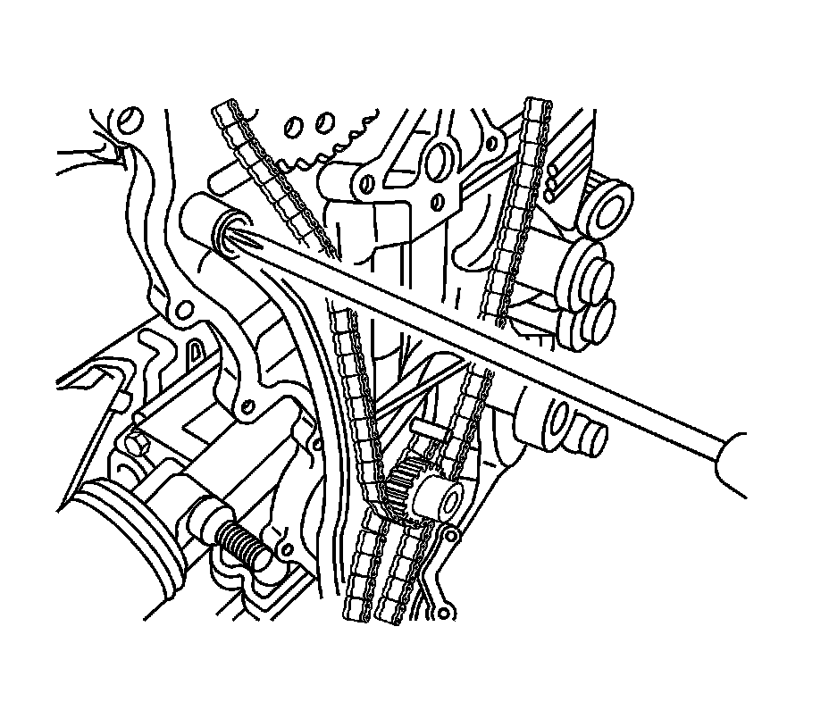
23. Remove the timing chain lever.
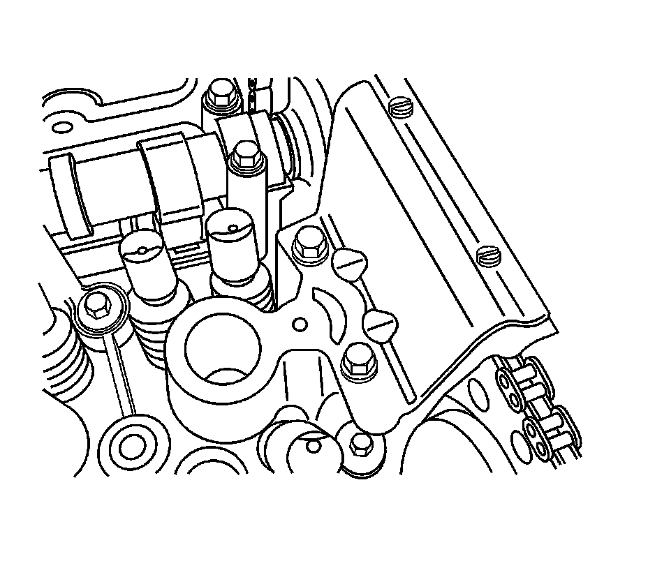
24. Remove the top timing chain guide.
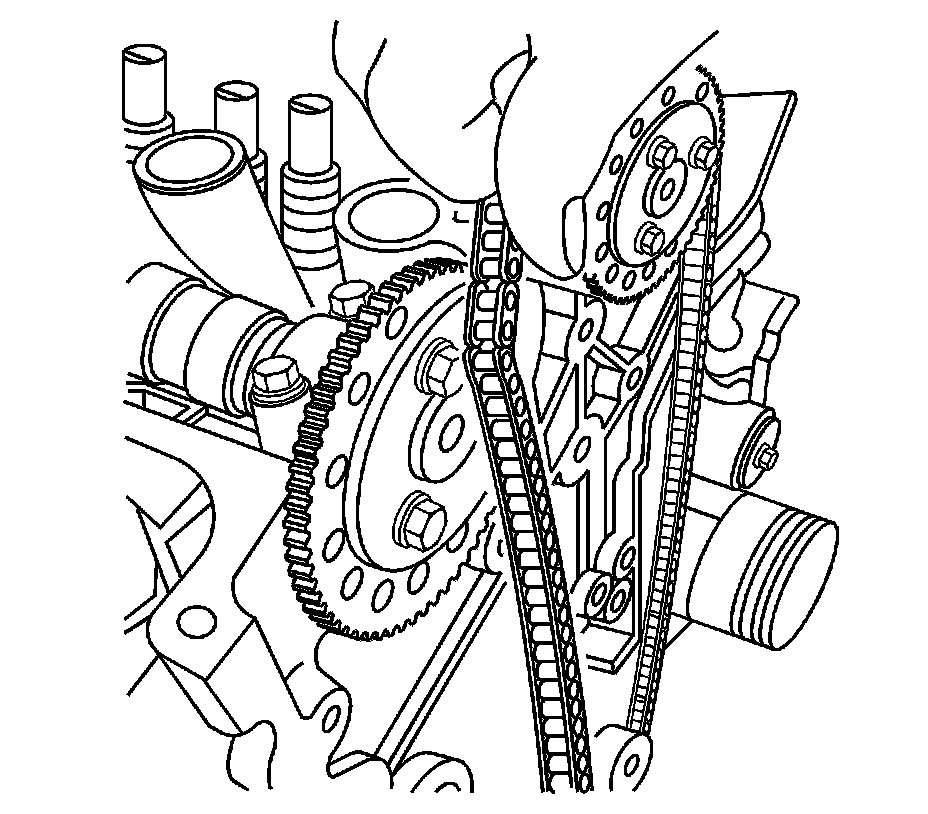
25. Remove the timing chain
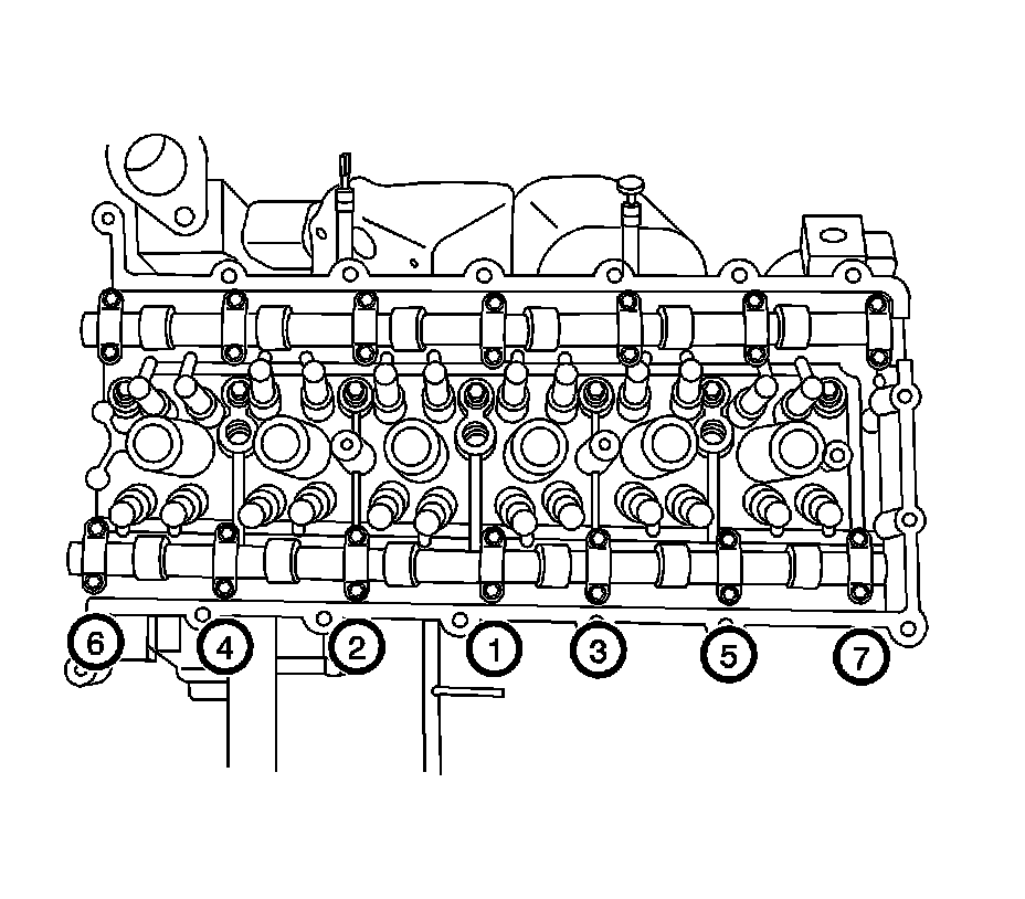
26. Gradually remove the camshaft cap bolts in sequence.
27. Remove the intake camshaft.
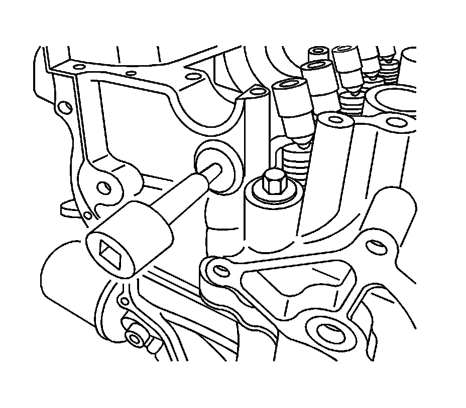
28. Install the rocker arm shaft plug removal tool.
29. Remove the rocker arm shaft plugs at the end of the cylinder head.
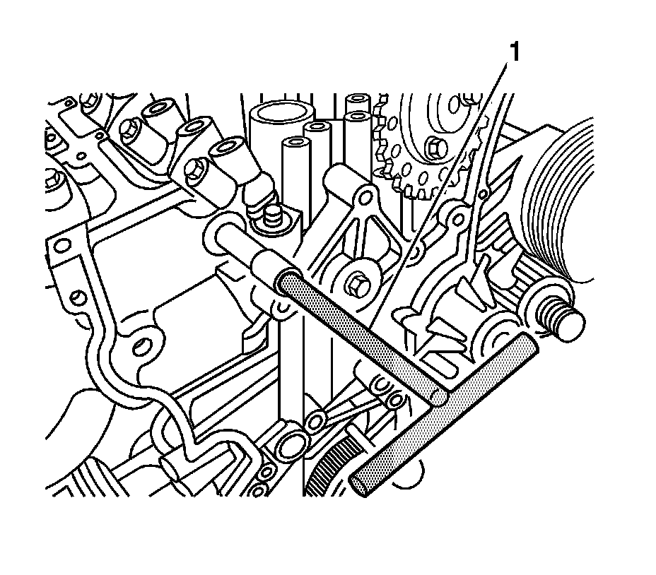
30. Using EN-47614 (1), remove the front/rear rocker arm shafts.
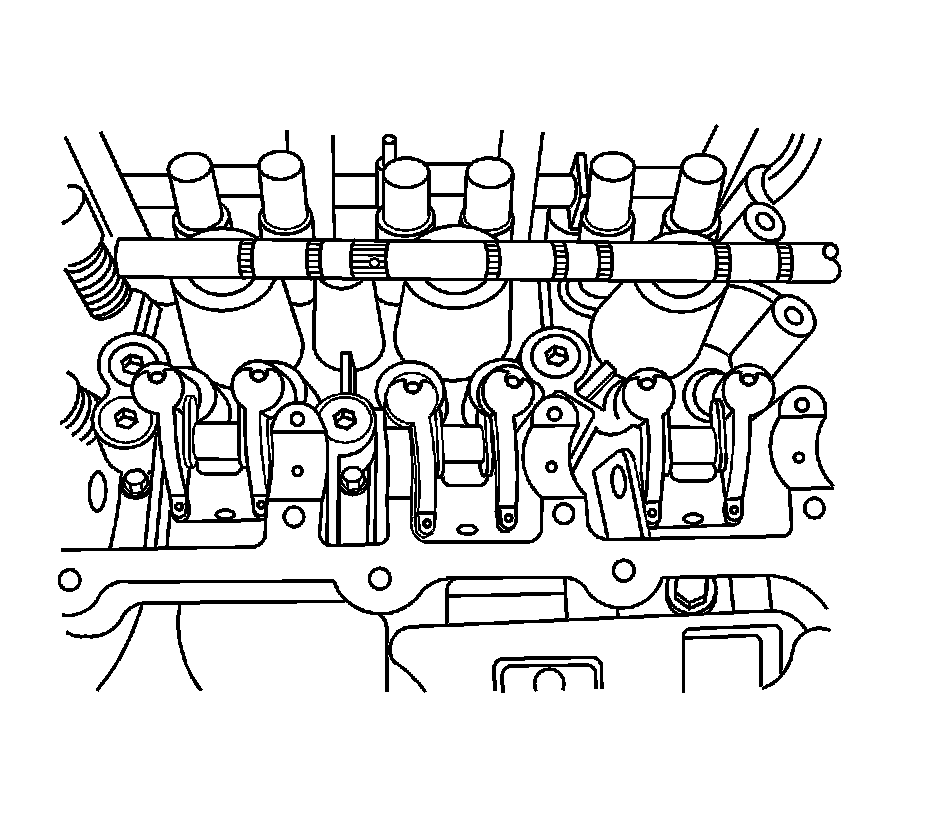
31. Remove the rocker arms.
32. Soak the rocker arms and shafts in engine oil.
Installation Procedure
1. Place the rocker arms on the cylinder head.
Important:
* The front rocker arm shaft which will be installed to the timing chain side can be identified by the hole for the rocker arm spring.
* To prevent damage to the rocker arm shaft, rotate the rocker arm shaft right and left when installing.
2. Using EN-47614 , install the front/rear rocker shaft into the cylinder head.
3. Apply sealant to the rocker arm shaft plugs.
4. Install the rocker arm shaft plugs.
Tighten the plugs to 40 Nm (29 lb ft).
Important:
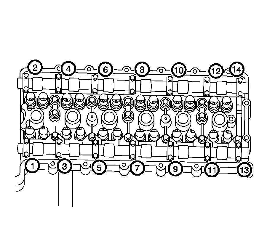
The intake camshaft has one groove which is marked between cam No. 1 and Journal No. 2. The exhaust camshaft has 2 grooves.
5. Position the intake and exhaust camshafts.
Important:
When installing the camshaft caps, the arrow mark on the camshaft caps should be directed to the intake or exhaust camshaft sprocket.
6. Install the exhaust camshaft caps in sequence.
Tighten the camshaft caps to 12 Nm (9 lb ft).
Important:
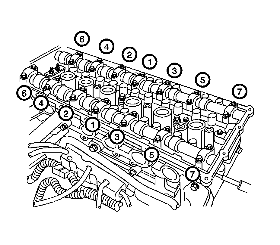
When installing the camshaft caps, the arrow mark on the camshaft caps should be directed to the intake or exhaust camshaft sprocket.
7. Tighten the intake camshaft caps in sequence.
Tighten the camshaft caps to 12 Nm (9 lb ft).
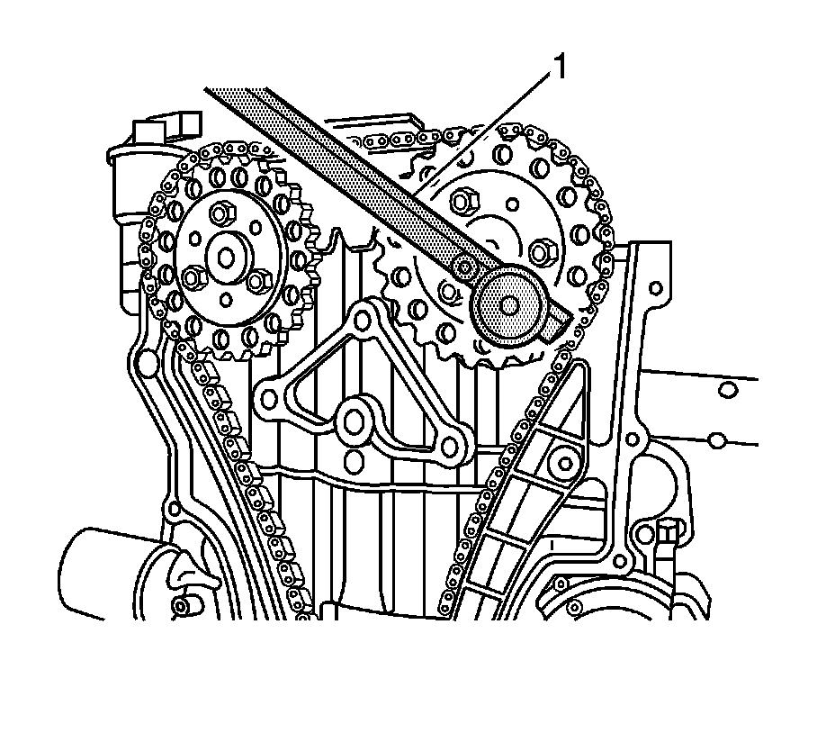
8. Using EN-47613 (1), align both marks on the camshaft sprockets and on the timing chain, then install the timing chain.
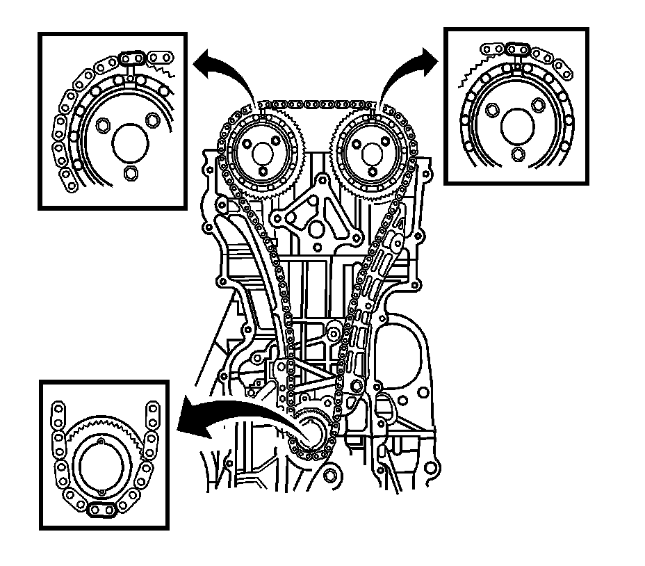
9. Ensure the timing marks on the timing chain are aligned with the marks on the intake and exhaust camshaft sprockets and the crankshaft sprocket.
10. Position the timing chain guide.
11. Install the timing chain guide bolts.
Tighten the timing chain guide bolts to 20 Nm (15 lb ft).
12. Position the timing chain lever.
13. Install the timing chain lever bolt.
Tighten the timing chain lever bolt to 20 Nm (15 lb ft).
14. Position the timing chain tensioner.
15. Install the timing chain tensioner bolts.
Tighten the timing chain tensioner bolts to 20 Nm (15 lb ft).
16. Position the timing chain top guide.
17. Install the timing chain top guide bolts.
Tighten the timing chain top guide bolts to 10 Nm (89 lb in).
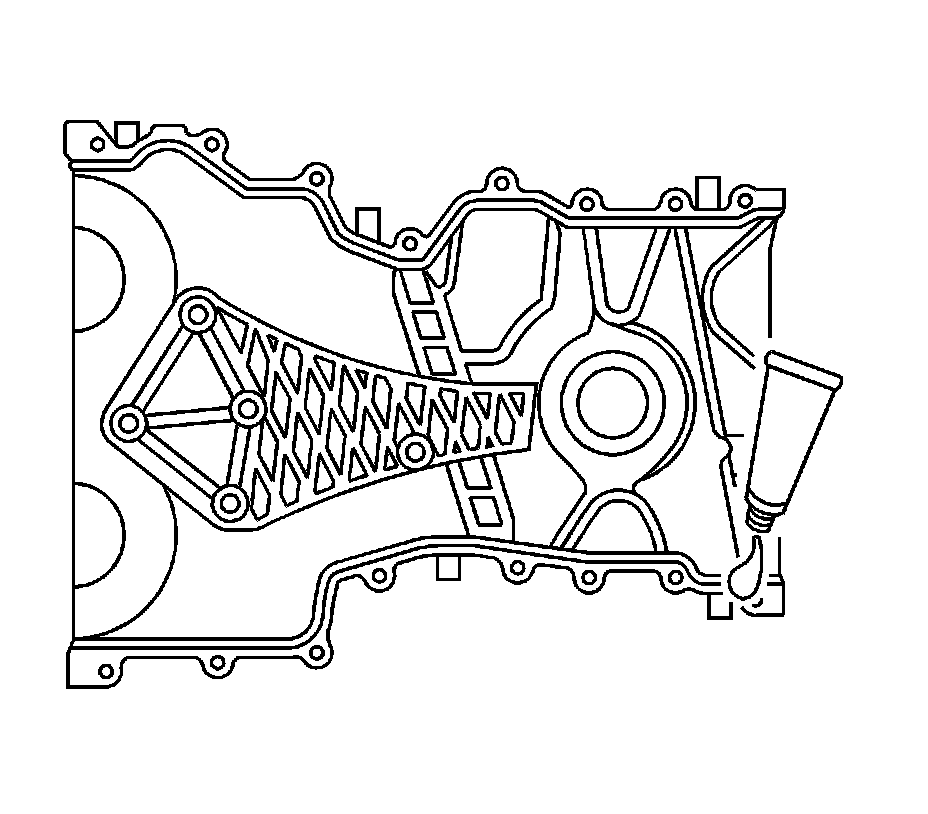
18. Install two timing chain dowel rings.
19. Apply liquid gasket (Loctite 5900-M8585) on the timing chain cover.
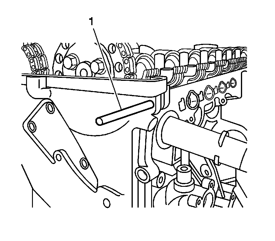
20. Using timing chain cover guide pins EN-47612 (1), install the timing chain cover
21. Install the timing chain cover bolts.
1. Tighten the center timing chain cover bolt to 20 Nm (15 lb ft).
2. Tighten all other timing chain cover bolts to 8 Nm (70 lb in).
22. Position the oil pan.
23. Install the oil pan bolts.
Tighten the oil pan bolts to 8 Nm (70 lb in).
24. Position the water pump pulley.
25. Install the water pump pulley bolts.
Tighten the water pump pulley bolts to 10 Nm (89 lb in).
26. Position the engine mount bracket support.
27. Install the engine mount bracket support bolts.
Tighten the engine mount bracket support bolts to 28 Nm (21 lb ft).
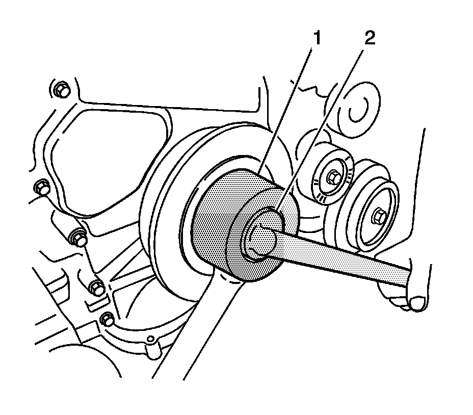
28. Install the crankshaft pulley and the crankshaft pulley bolt.
29. Using EN-47610 (1), and EN-47611 (2), tighten the crankshaft pulley bolt.
Tighten the crankshaft pulley bolt to 550 Nm (406 lb ft).
30. Install the drive belt.
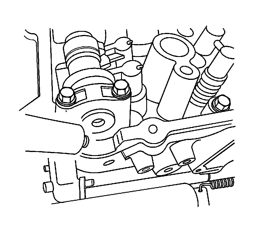
31. Apply liquid gasket on the surface of the cylinder head.
32. Install the cylinder head cover and the cylinder head cover bolts.
Tighten the cylinder head cover bolts to 13 Nm (10 lb ft).
33. Install the ignition coil and the ignition coil retaining bolts (1).
Tighten the ignition coil retaining bolts to 7 Nm (62 lb in).
34. Connect the fuel injectors (1).

35. Discard used intake manifold gaskets and install new ones.
Important:
Install the intake manifold after installing the fuel rail.
36. Install the intake manifold.
37. Install the intake manifold retaining nuts and bolts.
* Tighten the 7 intake manifold retaining bolts to 12 Nm (106 lb in).
* Tighten the 4 intake manifold retaining nuts to 12 Nm (106 lb in).
38. Position the VIS vacuum tank (1).
39. Install the VIS vacuum tank bolts.
Tighten the VIS vacuum tank bolts to 8 Nm (71 lb in).
40. Position the front support bracket (1).
41. Install the front support bracket mounting bolts.
Tighten the front support bracket mounting bolts to 20 Nm (15 lb ft).
42. Position the rear support bracket.
43. Install the rear support bracket mounting bolts and the rear support bracket (1).
Tighten the rear support bracket mounting bolts to 20 Nm (15 lb ft).
44. Connect the PCV hose.
45. Position the EGR pipe and gasket to the EGR valve adapter.
46. Install the EGR pipe mounting bolts (1).
Tighten EGR pipe mounting bolts to 10 Nm (89 lb in).
47. Install the engine assembly. Refer to Engine Replacement Removal and Replacement.