Timing Chain: Service and Repair
Timing Chain, Sprockets, and/or Tensioner Replacement
Tools Required
J 45027 Tensioner Tool
Removal Procedure
1. Remove the camshaft cover.
2. Raise and support the vehicle. Refer to Lifting and Jacking the Vehicle.
3. Remove the engine front cover.
Important: To rotate the camshaft, use a 24 mm open-end wrench on the camshaft flats. Camshaft should be rotated in a clockwise direction only, facing camshaft sprockets from the passenger side of the vehicle.
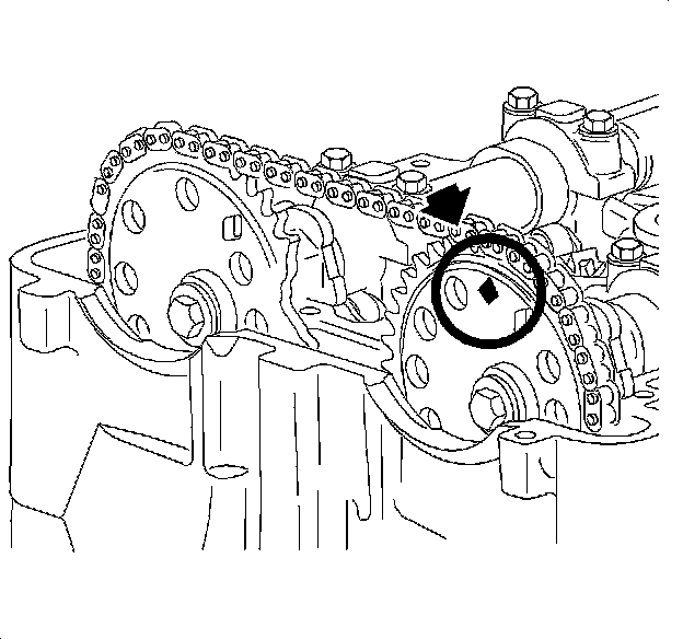
5. Locate the No. 1 piston to approximately 60 degrees before top dead center (diamond shaped hole on intake camshaft sprocket at 12 o'clock position). Remove the spark plugs. This will ease the rotation effort.
6. Remove the timing chain tensioner.
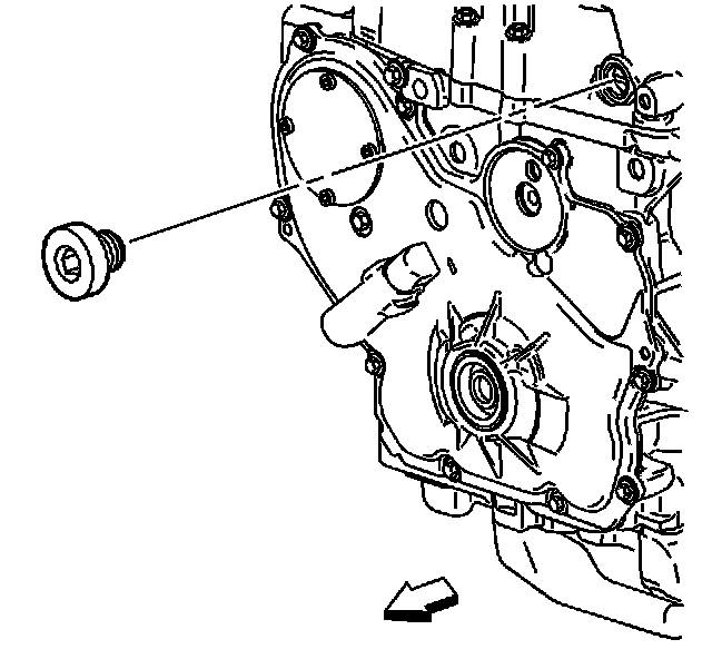
7. Remove the fixed timing chain guide access plug.
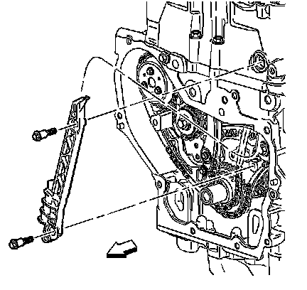
8. Remove the fixed timing chain guide.
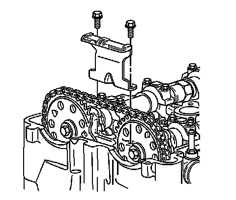
9. Remove the upper timing chain guide.
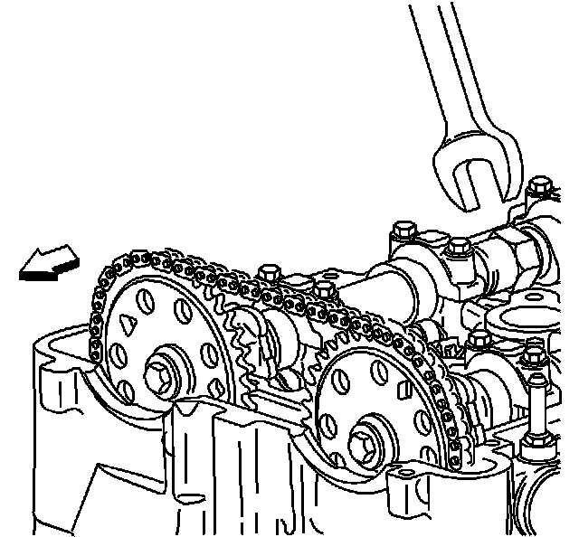
10. Use a 24 mm wrench to hold the camshafts from turning.
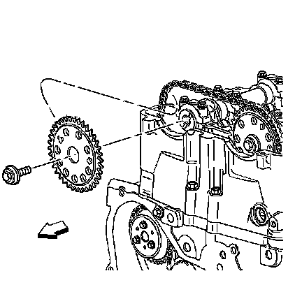
11. Remove the exhaust camshaft sprocket bolt and discard.
12. Remove the exhaust camshaft sprocket.
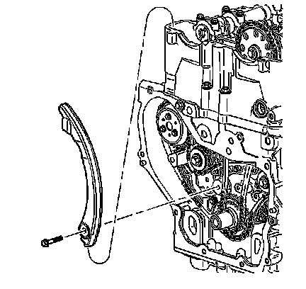
13. Remove the timing chain tensioner guide.
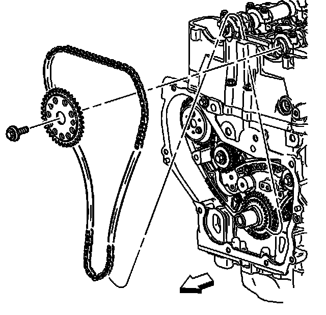
14. Remove the intake camshaft sprocket bolt and discard.
15. Remove the intake camshaft sprocket.
16. Remove the timing chain through the top of the cylinder head.
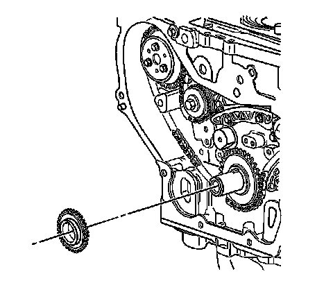
17. Remove the crankshaft sprocket.
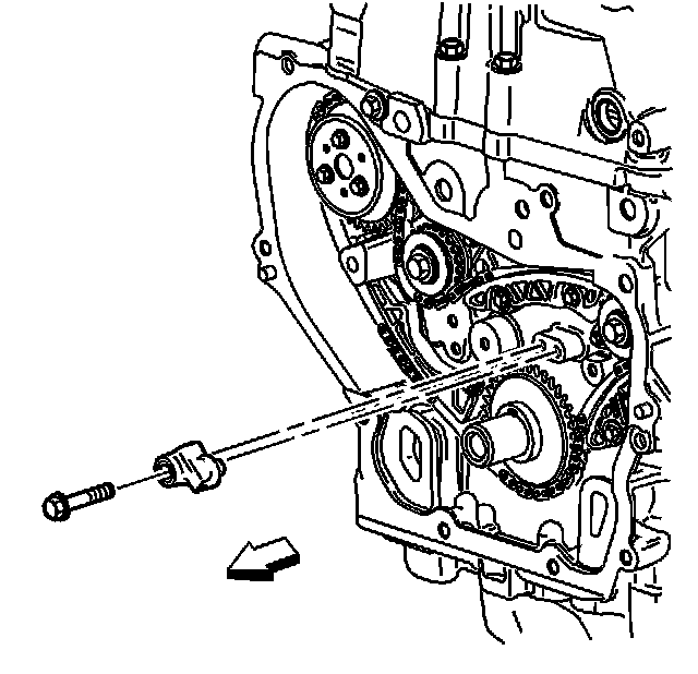
18. Remove the oil nozzle and bolt.
19. Remove the balance shaft drive chain tensioner.
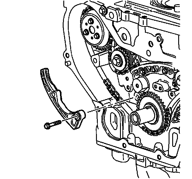
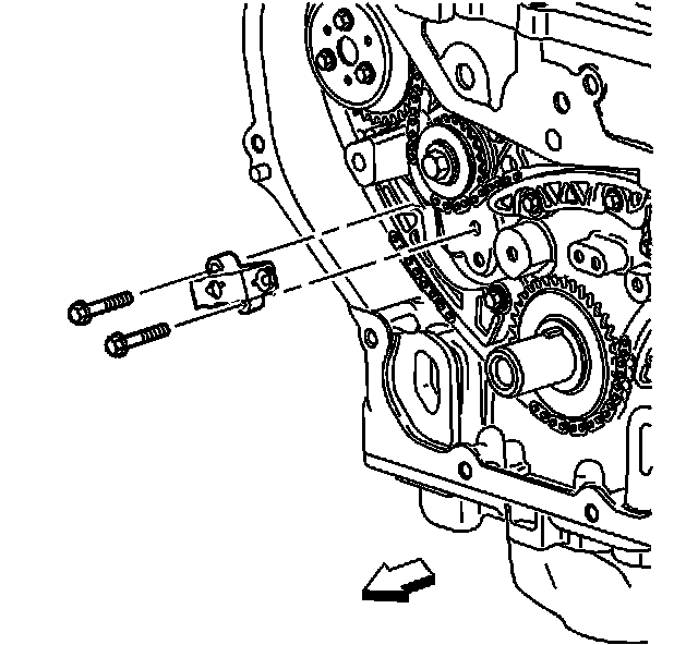
20. Remove the adjustable balance shaft chain guide.
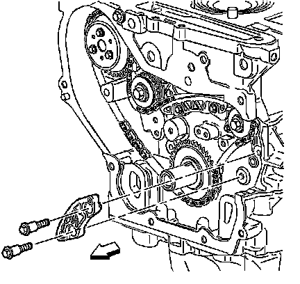
21. Remove the small balance shaft drive chain guide.
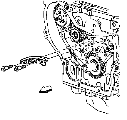
22. Remove the upper balance shaft drive chain guide.
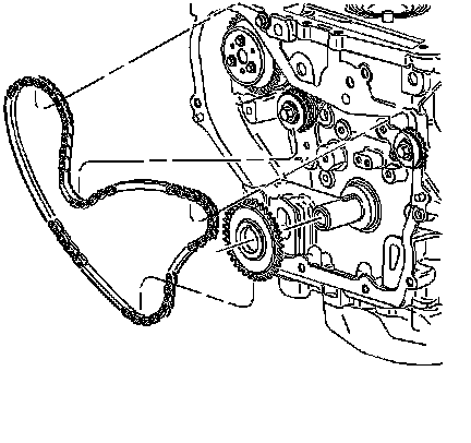
Important: It may ease removal of the balance shaft drive chain to get all of the slack in the chain between the crankshaft and water pump sprockets.
23. Remove the balance shaft drive chain.
Installation Procedure
Notice: Refer to Fastener Notice.
Important: If the balance shafts are not properly timed to the engine, the engine may vibrate and make noise.
1. Install the upper balance shaft chain guide.
Tighten the upper balance shaft chain guide bolts to 15 N.m (11 lb ft).
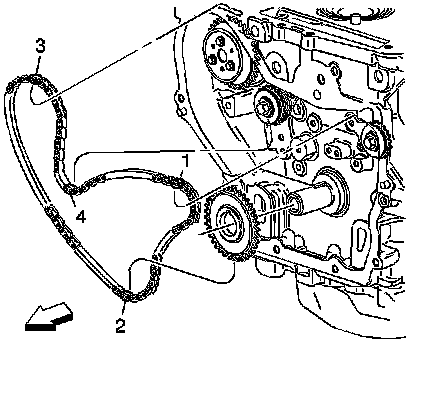
2. Install the balance shaft drive chain with the colored links lined up on with the marks on the balance shaft drive sprockets and the crankshaft sprocket. Use the following procedure to line up the links with the sprockets:
Orient the chain so that the copper colored and chrome links are visible.
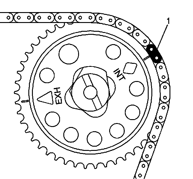
1. Place the uniquely colored link (1) so that it lines up with the timing mark on the intake side balance shaft sprocket.
2. Working clockwise around the chain, place the first matching colored link (2) in line with the timing mark on the crankshaft drive sprocket. (approximately 5 o'clock position on the crank sprocket).
3. Place the chain (3) on the water pump drive sprocket (alignment is not critical).
4. Align the last matching colored link (4) with the timing mark on the exhaust side balance shaft drive sprocket.
3. Install the small balance shaft chain guide.
4. Tighten the balance shaft chain guide bolts.
Tighten the chain guide bolts to 15 N.m (11 lb ft).
5. Install the adjustable balance shaft drive chain guide.
Tighten the chain guide bolts to 10 N.m (89 lb in).
6. Turn the tensioner plunger 90 degrees in its bore and compress the plunger until a paper clip can be inserted through the hole in the plunger body and into hole in the tensioner plunger.
7. Install the timing chain tensioner.
8. Tighten the chain tensioner bolts.
Tighten the chain tensioner bolts to 10 N.m (89 lb in).
9. Remove the paper clip from the balance shaft drive chain tensioner.
10. Install the oil nozzle and bolt.
Tighten the oil nozzle bolt to 10 N.m (89 lb in).
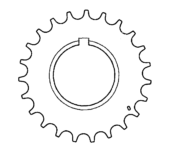
11. Install the crankshaft sprocket with timing mark at the 5 o'clock position.
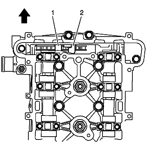
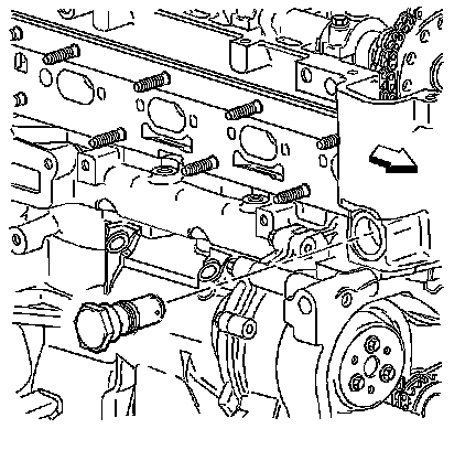
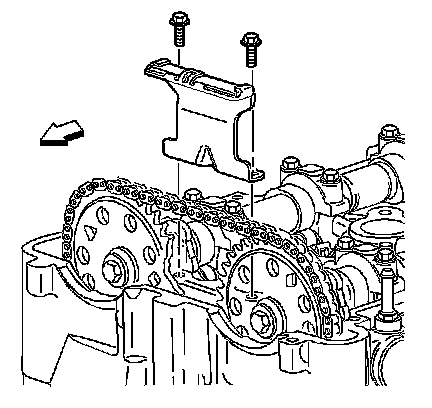
12. Lower the timing chain through the opening in the top of the cylinder head. Carefully ensure that the chain goes around both sides of the cylinder block bosses (1, 2).
13. Install the intake camshaft sprocket with the INT diamond at the 2 o'clock position.
Important: Always install NEW sprocket bolts.
14. Hand tighten a NEW intake camshaft sprocket bolt.
15. Route the timing chain around the crankshaft sprocket with the matching colored link aligning with the timing mark.
16. Route the timing chain around the intake camshaft sprocket with the uniquely colored link (1) aligning with the INT diamond.
17. Install the timing chain tensioner guide through the opening in the top of the cylinder head.
Tighten the timing chain tensioner guide bolt to 10 N.m (89 lb in).
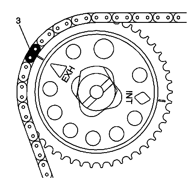
18. Install the exhaust camshaft sprocket with the timing chain matching colored link (3) at EXH triangle aligned at the 10 o'clock position.
19. Use a 24 mm wrench to rotate the camshaft slightly, until exhaust sprocket aligns with the camshaft.
Important: Always install NEW sprocket bolts.
20. Hand tighten the NEW exhaust camshaft sprocket bolt.
21. Install the fixed timing chain guide.
Tighten the fixed timing chain bolts to 10 N.m (89 lb in).
22. Apply sealant compound to thread and install the timing chain guide bolt access hole plug. Refer to Sealers, Adhesives, and Lubricants for the correct part number.
Tighten the chain guide plug to 90 N.m (59 lb ft).
23. Install the timing chain upper guide.
Tighten the timing chain upper guide bolts to 10 N.m (89 lb in).
24. Inspect the timing chain tensioner. If the timing chain tensioner, O-ring seal, or washer is damaged, replace the timing chain tensioner.
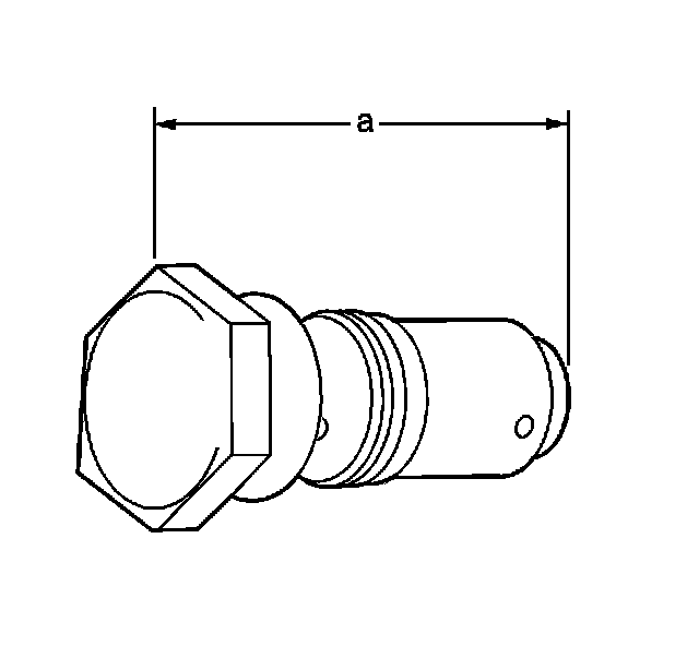
25. Measure the timing chain tensioner assembly from end to end.
A new tensioner should be supplied in the fully compressed non-active state. A tensioner in the compressed state will measure 72 mm (2.83 in) (a) from end to end. A tensioner in the active state will measure 85 mm (3.35 in) (a) from end to end.
26. If the timing chain tensioner is not in the compressed state, perform the following steps:
1. Remove the piston assembly from the body of the timing chain tensioner by pulling it out.
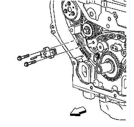
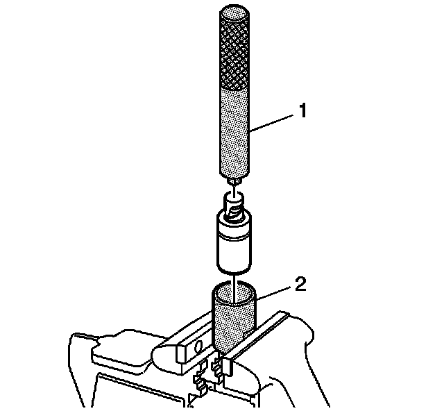
2. Install the J 45027-2 (2) into a vise.
3. Install the notch end of the piston assembly into the J 45027-2 (2).
4. Using the J 45027-1 (1), turn the ratchet cylinder into the piston.
27. Inspect the bore of the tensioner body for dirt, debris, and damage. If any damage appears, replace the tensioner. Clean dirt or debris out with a lint-free cloth.
28. Install the compressed piston assembly back into the timing chain tensioner body until it stops at the bottom of the bore. Do not compress the piston assembly against the bottom of the bore. If the piston assembly is compressed against the bottom of the bore, it will activate the tensioner, which will then need to be reset again.
29. At this point the tensioner should measure approximately 72 mm (2.83 in) (a) from end to end. If the tensioner does not read 72 mm (2.83 in) (a) from end to end repeat steps 26.1 through 26.4.
30. Install the timing chain tensioner.
Tighten the timing chain tensioner to 75 N.m (55 lb ft).
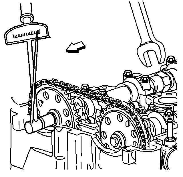
31. Use a suitable tool with a rubber tip on the end. Feed the tool down through the camshaft drive chain to rest on the timing chain. Then give a sharp jolt diagonally downwards to release the tensioner.
32. Use a 24 mm wrench to hold the camshaft.
Tighten the NEW camshaft bolts to 85 N.m (63 lb ft) plus 30 degrees.
33. Install the camshaft cover.
34. Raise the vehicle. Refer to Lifting and Jacking the Vehicle.
35. Install the engine front cover.
36. Lower the vehicle.