Power Windows Inoperative - All (Sedan)
POWER WINDOWS INOPERATIVE - ALL (SEDAN)
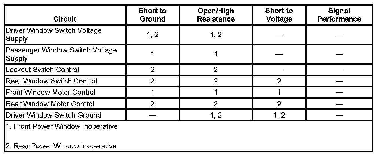
DIAGNOSTIC FAULT INFORMATION
Perform the System Check - Vehicle prior to using this diagnostic procedure. Initial Inspection and Diagnostic Overview
CIRCUIT/SYSTEM DESCRIPTION
The power window system will operate any time the ignition is the ACC or RUN position. The power window system will also operate whenever the body control module (BCM) is in Accessory Delay Module (RAP) mode. The driver power window switch contains individual window switches for each of power windows. All windows may be controlled up and down from the driver power window switch. The individual passenger power window switches will only control the up and down operation of their respective power window.
Each power window contains a reversible power window motor. The direction the window travels is dependent upon the polarity of the supply voltage. By reversing polarity of the supply voltage the window motor will move up or down. Each power window motor is internally circuit breaker protected.
Battery voltage is supplied to the power window switch through the accessory voltage supply circuit. The power window switch also receives a constant ground source. The power window motor control circuits are connected to ground through the normally closed up and down contacts of the power window switch. When the power switch is placed in the down position, the power window motor down control circuit is switched to 12 volts and is applied to the down side of the power window motor. Since the other side of the power motor is connected to ground through the normally closed contacts of the up switch, the window travels down. By placing the power window switch in the up position, the polarity of the power window motor is reversed and the window travels up.
The driver window switch has an express-down feature that allows the window to be lowered completely without holding the switch. The switch is labeled AUTO. Press the front of the switch part way and release it and the driver window will open a small amount. Press the switch down all the way and release it and the window will go completely down automatically.
To stop the window while it is lowering, pull the front of the switch up.
CIRCUIT/SYSTEM VERIFICATION
1. Ignition ON, command the appropriate door window UP and DOWN by pressing the appropriate window switch. Observe the operation of the appropriate door windows
- If all power windows are inoperative, refer to All power windows Inoperative.
- If the front driver door window is inoperative, refer to Driver power window Inoperative.
- If the right front or left rear or right rear door window is inoperative, refer to passenger power window Inoperative.
- If both rear door windows are inoperative, refer to lockout switch malfunction.
2. Ignition ON, command the express down function door window by pressing Auto on the driver window switch past the first detent and releasing. The driver's window should roll completely down.
- If the driver window fails to roll completely down, replace the driver window switch.
CIRCUIT/SYSTEM TESTING
Lockout Switch Malfunction
1. Ignition ON, activate the lockout parameter by pressing the lockout switch on the driver window switch. Command each of the rear passenger windows UP and DOWN using the appropriate rear door passenger window switches. Both rear door passenger window switches should be inoperative.
- If both rear passenger windows continue to function, test or replace the driver window switch.
2. Ignition ON, deactivate the lockout parameter my pressing the Lockout Switch on the driver window switch. Command each of the rear passenger windows UP and DOWN using the appropriate rear door passenger window switches. Both rear door passenger windows should function UP and DOWN as commanded.
- If both rear windows are inoperative, test or replace the driver window switch.
All Power Windows Inoperative
1. Ignition OFF, disconnect the B+ harness connector at the driver window switch.
2. Ignition OFF, test for less than 1 ohm of resistance between the ground circuit terminal B and ground.
- If greater than the specified range, test the ground circuit for an open/high resistance.
3. Ignition ON, verify that a test lamp illuminates between the B+ circuit terminal E and ground.
- If the test lamp does not illuminate, test the B+ circuit for an open/high resistance. If the PWR WNDW fuse is open, check the B+ circuit for a short to ground. If the circuit tests normal, replace the BCM.
4. If all circuits test normal, test or replace the driver window switch.
Driver Power Window Inoperative
1. Ignition OFF, disconnect the harness connector at the driver window motor.
2. Ignition OFF, test for less than 1 ohm of resistance between the control circuit terminal A and ground.
- If greater than the specified range, test the control circuit for a short to voltage or an open/high resistance. If circuits test normal, replace the driver window switch.
3. Ignition OFF, test for less than 1 ohm of resistance between the control circuit terminal B and ground.
- If greater than the specified range, test the control circuit for a short to voltage or an open/high resistance. If circuits test normal, replace the driver window switch.
4. Connect a test lamp between control circuit terminal A and control circuit terminal B.
5. Command the driver window UP and DOWN by pressing the driver window switch. The test lamp should turn ON when commanding the UP and DOWN states.
- If the test lamp remains OFF during either of the commands, test for a short to ground on either control circuit. If the circuits test normal, replace the driver window switch.
6. If all circuits test normal, test or replace the driver window motor.
Passenger Power Window Inoperative
1. Ignition OFF, disconnect the harness connector at the appropriate passenger window switch.
2. Ignition ON, verify that a test lamp illuminates between the B+ circuit terminal A and ground.
- If the test lamp does not illuminate and the Lockout Switch is CLOSED, test the B+ circuit for an open/high resistance.
3. Ignition OFF, test for less than 1 ohm of resistance between the control circuit terminal H and ground.
- If greater than the specified range, test the control circuit for a short to voltage or an open/high resistance. If circuits test normal, replace the driver window switch.
4. Ignition OFF, test for less than 1 ohm of resistance between the control circuit terminal D and ground.
- If greater than the specified range, test the control circuit for a short to voltage or an open/high resistance. If circuits test normal, replace the driver window switch.
5. Connect a test lamp between the control circuit terminal D and control circuit terminal H.
6. Ignition ON, command the appropriate passenger window UP and DOWN by pressing the appropriate window control on the driver window switch. The test lamp should illuminate during either of the commands.
- If the test lamp is always OFF, test for a short to ground on either control circuit. If all circuits test normal, test or replace the driver window switch.
7. Ignition OFF, reconnect the appropriate passenger window switch.
8. Ignition OFF, disconnect the harness connector at the appropriate passenger window motor.
9. Ignition OFF, test for less than 1 ohm of resistance between the control circuit terminal A and ground.
- If greater than the specified range, test the control circuit for a short to voltage or an open/high resistance. If circuits test normal, replace the appropriate passenger window switch.
10. Ignition OFF, test for less than 1 ohm of resistance between the control circuit terminal B and ground.
- If greater than the specified range, test the control circuit for a short to voltage or an open/high resistance. If circuits test normal, replace the appropriate passenger window switch.
11. Connect a test lamp between control circuit terminal A and control circuit terminal B.
12. Ignition ON, command the appropriate passenger window UP and DOWN by pressing the appropriate passenger window switch. The test lamp should turn ON when commanding the UP and DOWN states.
- If the test lamp remains OFF during either of the commands, test for a short to ground on either control circuit. If the circuits test normal, test or replace the appropriate passenger window switch.
13. If all circuits test normal, test or replace the appropriate passenger window motor.
COMPONENT TESTING
Driver Window Switch
1. Ignition OFF, disconnect the harness connector at the driver window switch.
2. Test for infinite resistance between the signal terminals E and F and the B+ circuit terminal B with the LR Switch in the INACTIVE position.
- If less than infinite resistance, replace the driver window switch.
3. Test for less than 2 ohms of resistance between the signal terminal E and the B+ circuit terminal B with the switch in the UP position.
- If greater than 2 ohms, replace the driver window switch.
4. Test for less than 2 ohms of resistance between the signal terminal F and the B+ circuit terminal B with the switch in the DOWN position.
- If greater than 2 ohms, replace the driver window switch.
5. Test for infinite resistance between the signal terminals G and H and the B+ circuit terminal B with the RR Switch in the INACTIVE position.
- If less than infinite resistance, replace the driver window switch.
6. Test for less than 2 ohms of resistance between the signal terminal G and the B+ circuit terminal B with the switch in the UP position.
- If greater than 2 ohms, replace the driver window switch.
7. Test for less than 2 ohms of resistance between the signal terminal H and the B+ circuit terminal C with the driver window switch in the DOWN position.
8. If greater than 2 ohms, replace the driver window switch.
9. Test for infinite resistance between the signal terminals B and A and the B+ circuit terminal B with the passenger switch in the INACTIVE position.
- If less than infinite resistance, replace the driver window switch.
10. Test for less than 2 ohms of resistance between the signal terminal B and the B+ circuit terminal B with the switch in the UP position.
- If greater than 2 ohms, replace the driver window switch.
11. Test for less than 2 ohms of resistance between the signal terminal A and the B+ circuit terminal B with the switch in the DOWN position.
12. If greater than 2 ohms, replace the driver window switch.
13. Test for infinite resistance between the signal terminals C and D and the B+ circuit terminal B with the driver switch in the INACTIVE position.
- If less than infinite resistance, replace the driver window switch.
14. Test for less than 2 ohms of resistance between the signal terminal C and the B+ circuit terminal B with the switch in the UP position.
- If greater than 2 ohms, replace the driver window switch.
15. Test for less than 2 ohms of resistance between the signal terminal D and the B+ circuit terminal B with the switch in the DOWN position.
16. If greater than 2 ohms, replace the driver window switch.
Passenger Window Switch
1. Ignition OFF, disconnect the harness connector at the passenger window switch.
2. Test for infinite resistance between the signal terminals G and F and the B+ circuit terminal A with the switch in the INACTIVE position.
- If less than infinite resistance, replace the passenger window switch.
3. Test for less than 2 ohms of resistance between the signal terminal F and the B+ circuit terminal A with the switch in the UP position.
- If greater than 2 ohms, replace the appropriate passenger window switch.
4. Test for less than 2 ohms of resistance between the signal terminal G and the B+ circuit terminal A with the switch in the DOWN position.
- If greater than 2 ohms, replace the appropriate passenger window switch.
Window Motor
1. Install a 30-amp fused jumper wire between the control terminal A and 12 volts. Momentarily install a jumper wire between the control terminal B and ground. The appropriate window motor should perform the UP or DOWN function.
- If the function does not perform as specified, replace the appropriate window motor.
2. Reverse the jumper wires, the appropriate window motor should perform the DOWN or UP function.
- If the function does not perform as specified, replace the appropriate window motor.
REPAIR INSTRUCTIONS
Perform the Diagnostic Repair Verification after completing the diagnostic procedure. Verification Tests
- Front Side Door Window Switch Replacement - Left Side
- Front Side Door Window Switch Replacement - Right Side
- Front Side Door Window Regulator Motor Replacement
- Rear Side Door Window Regulator Motor Replacement
- Rear Side Door Window Switch Replacement