Evaporator Temperature Sensor / Switch: Description and Operation
DESCRIPTION
NOTE: Two different designs of evaporator temperature sensors are used depending on when the vehicle was built.
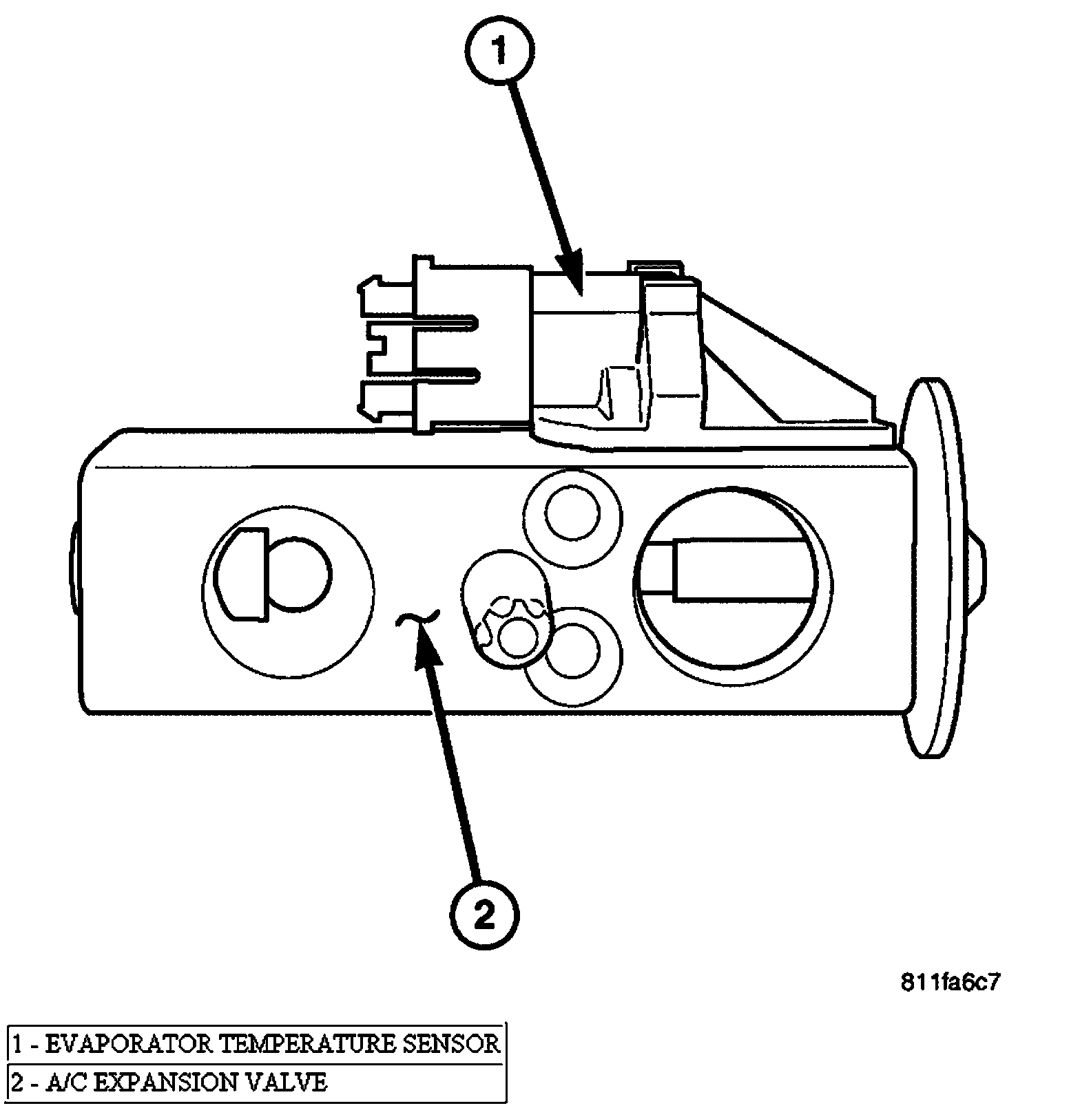
The evaporator temperature sensor used on early model year vehicles is installed on the top of the expansion valve in the right rear corner of the engine compartment and measures the temperature of the refrigerant leaving the A/C evaporator (Evaporator Temperature Sensor - Expansion Valve Mounted). The sensor has a small probe that is inserted in a small well in the body of the expansion valve that is filled with a special silicone-based thermal grease. A small molded plastic push-in retainer secures the sensor to a threaded hole in the top surface of the expansion valve. Two terminals within a molded plastic connector receptacle on the sensor connect it to the vehicle electrical system through a take out and connector of the HVAC wire harness.
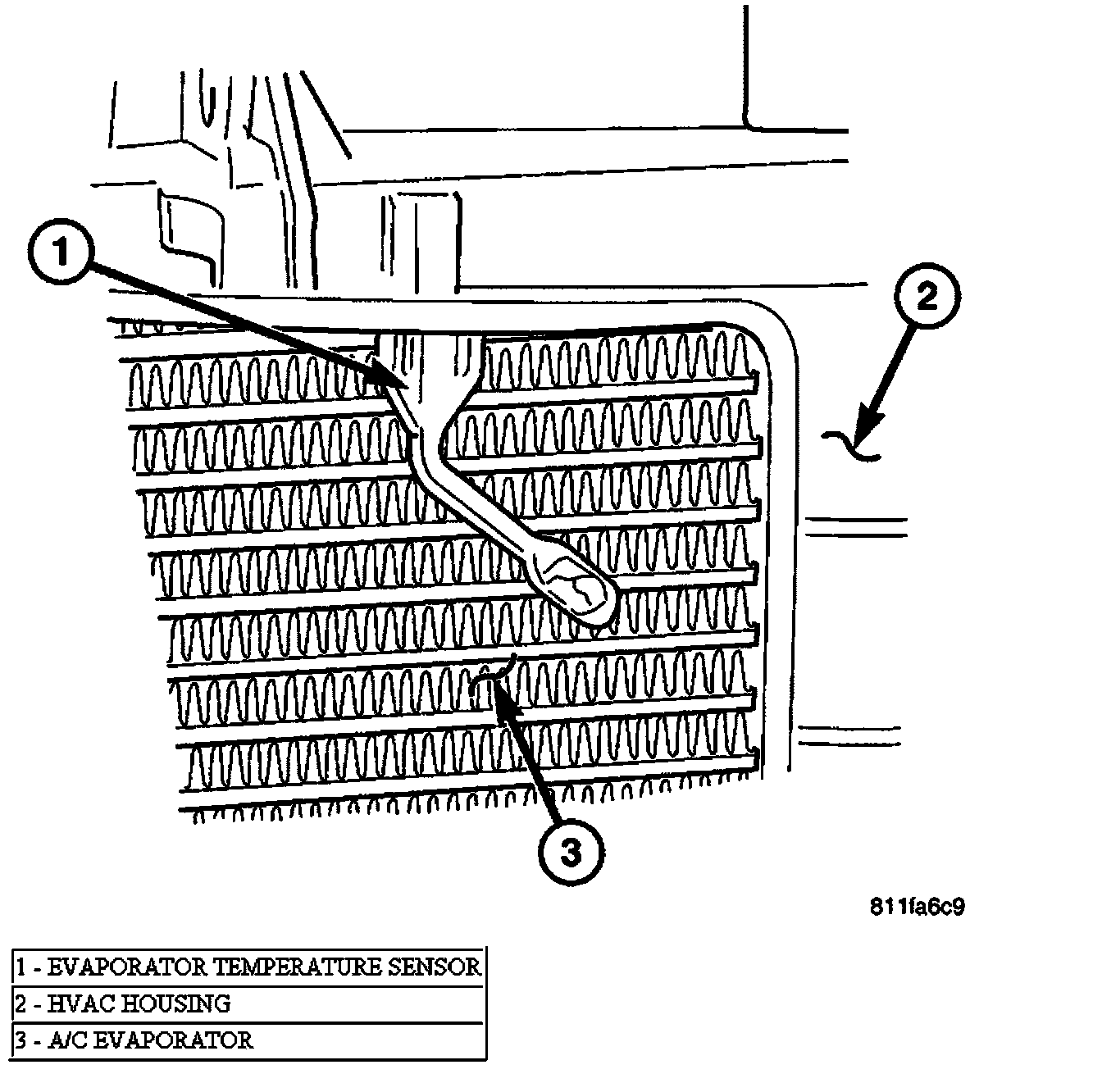
The evaporator temperature sensor used on late model year vehicles is installed on the top of the HVAC housing behind the instrument panel and measures the air temperature downstream of the evaporator (Evaporator Temperature Sensor - Downstream Probe Type). The sensor is an electrical thermistor in a plastic housing that is inserted into the HVAC housing. Two terminals within the molded plastic connector receptacle on the sensor connect it to the vehicle electrical system through a take out and connector of the HVAC wire harness.
OPERATION
The evaporator temperature sensor monitors the temperature of the refrigerant leaving the A/C evaporator or the conditioned air once it passes through the A/C evaporator (depending on when the vehicle was built). The evaporator temperature sensor will change its internal resistance in response to the temperatures it monitors and is connected to the A/C-heater control through sensor ground and signal circuits. As the refrigerant or conditioned air temperature increases, the resistance of the evaporator temperature sensor decreases and the voltage monitored by the A/C-heater control decreases.
The A/C-heater control uses this monitored voltage reading as an indication of evaporator temperature. The A/C-heater control is programmed to respond to this input by sending electronic messages to the powertrain control module (PCM) over the programmable communications interface (PCI) data bus, and the PCM then cycles the A/C compressor clutch as necessary to optimize A/C system performance and to protect the system from evaporator freezing.
The evaporator temperature sensor is diagnosed using the DRBIII� scan tool. Refer to Body Diagnostic Procedures.
The evaporator temperature sensor cannot be adjusted or repaired and must be replaced if found faulty or damaged.