Ignition Control Module: Testing and Inspection
NOTE: An analog-type circuit tester should be used.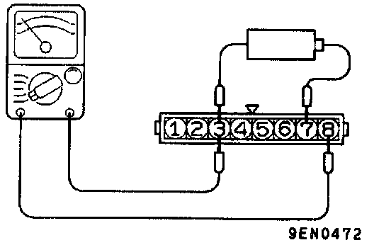
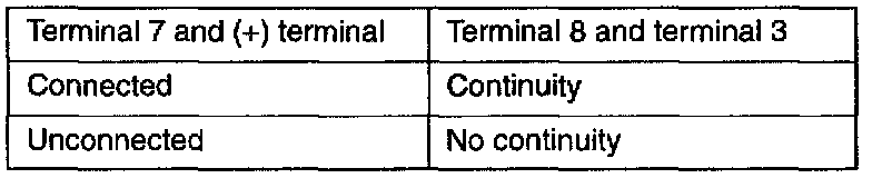
No. 1 - No. 4 coil side
1. Connect the negative (-) terminal of the 1 .5V power supply to terminal 3 of the ignition power transistor; then check whether there is continuity between terminal 8 and terminal 3 when terminal 7 and the positive (+) terminal are connected and disconnected.
NOTE: Connect the (-) probe of the circuit tester to terminal 8.
2. Replace the ignition power transistor if there is a malfunction.
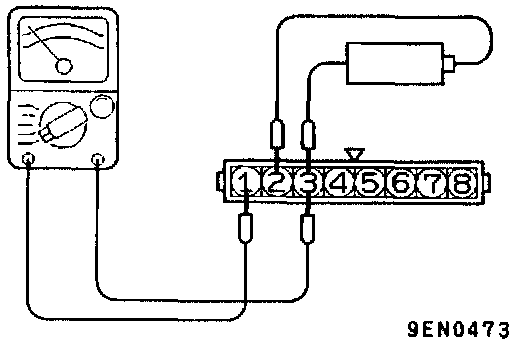
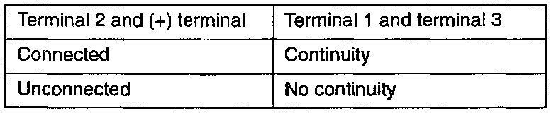
No. 2 - No. 3 coil side
1. Connect the negative (-) terminal of the 1 .5V power supply to terminal 3 of the ignition power transistor; then check whether there is continuity between terminal 1 and terminal 3 when terminal 2 and the positive (+) terminal are connected and disconnected.
NOTE: Connect the (-) probe of the ohmmeter to terminal 1.
2. Replace the ignition power transistor if there is a malfunction.