Fuel System - Connector Service Procedure
Article No. 85-19-20FUEL SYSTEM SERVICE PROCEDURE FOR NYLON FUEL TUBES AND PUSH CONNECT FITTINGS
LIGHT TRUCK 1985 RANGER, BRONCO II, E & F SERIES WITH EFI ENGINES
If services are required on vehicles equipped with nylon fuel tubes and EFI fuel systems, service parts and service procedures are being released. The following procedure clarifies Shop Manual Section 24-50 of the 1985 Truck Shop Manual, Engine - Volume B, and must be adhered to:
MAJOR SERVICE OPERATIONS
Fuel Lines
Vehicles equipped with nylon fuel tubes and push connect fittings have three types of service that can be performed to the fuel lines; replacing nylon tubing (splicing nylon to nylon), replacing push connector and replacing damaged push connect tube end. These three methods follow:
Splicing Nylon to Nylon
1. Relieve fuel system pressure as outlined in the 1985 Car/Truck Shop Manual - Powertrain Section 24-50. Read cautionary note prior to relieving pressurized fuel system.
2. Cut out damaged section of tubing and retain as a guide.
3. Cut a section of nylon service tubing (type 11 or 12 available in 5/16 and 3/8 inch sizes) to the same length as the damaged section of tubing.
Figure 23 - Tubing Splice:
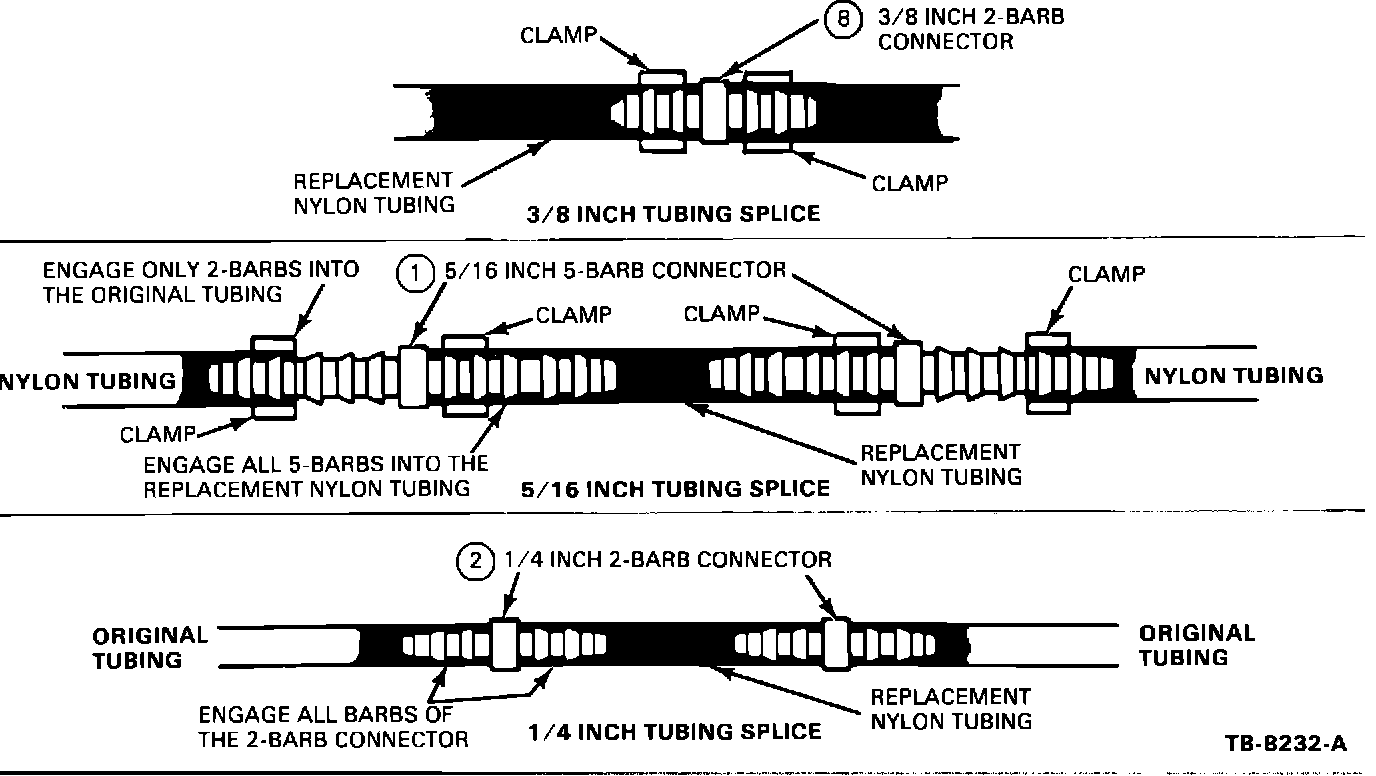
4. Select the proper (5/16 and 3/8 inch) barbed connectors for completing the splice. Two connectors are required for each splice (Figure 23).
NOTE: To make hand insertion of the barbed connectors into the nylon easier, the tube end must be soaked in a cup of boiling water for one minute immediately before pushing the barbs into the nylon. Refer to Figure 23 for all splicing service combinations.
5. Install the barbed connectors into each end of the replacement tubing using boiling water as outlined.
6. Install clips onto any tubes which might be difficult to access once the final splices are completed.
a. Install four (4) Keystone clamps (part number 377931) onto the original nylon tubing (loosely) before beginning Step 7.
7. Complete the splice of the replacement nylon to the original nylon tubing at both ends. (Use the boiling water method mentioned previously, to get the required number of barbs engaged, as shown in Figure 23).
a. Tighten the clamps in the locations shown in Figure 23.
8. Install any remaining clips which were removed for this service and check that the tubes are secure in the original clips.
9. Start engine and check for leaks.
Replacing Damaged Push Connectors
1. Relieve fuel system pressure as outlined in the 1985 Car/Truck Shop Manual - Powertrain Section 24-50. Read cautionary note prior to relieving pressurized fuel system.
NOTE: Damaged push connectors must be discarded and replaced with new push connectors. If only the retaining clip is damaged, replace the clip.
2. Disconnect the damaged push connector. Be sure to bend the shipping tab to the side before removing retaining clip.
Figure 22 - FUEL LINE SERVICE PARTS:
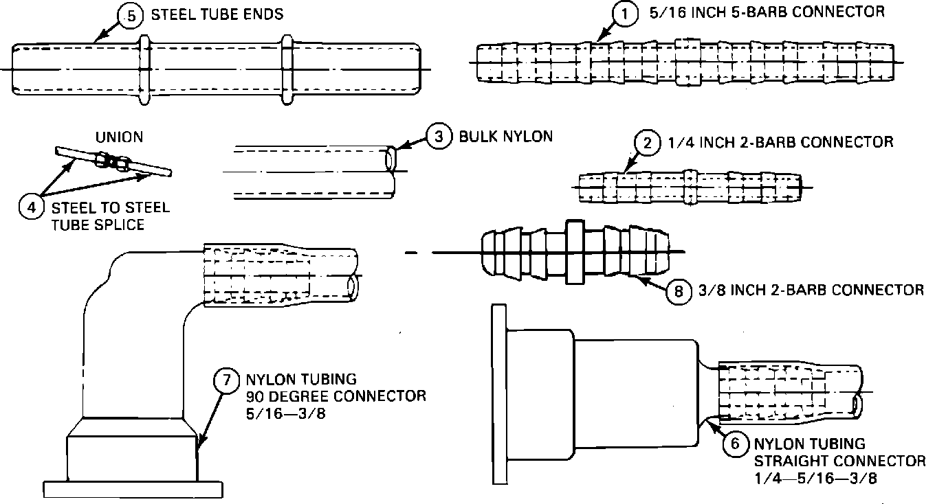
3. Select the proper size replacement push connector and nylon tube assembly (Figure 22).
4. Cut out a section of the original nylon tube to the same length as the nylon tube attached to the new push connector.
5. Install proper barbed connector into the replacement nylon assembly.
Figure 23 - Tubing Splice:
NOTE: To make hand insertion of the barbed connectors into the nylon easier, the tube end must be soaked in a cup of boiling water for one minute immediately before pushing the barbs into the nylon. Refer to Figure 23 for all splicing service combinations.
a. Put two (2) Keystone clamps (part number 377931) onto the original nylon tubing (loosely) before beginning Step 6.
6. Complete the splice by connecting the barbed connector to the original nylon. Refer to Figure 23 for the proper barb insertion.
a. Tighten the clamps in the locations shown in Figure 23.
7. Connect the new connector assembly to the steel tube end. Pull back on the connection to insure that the fittings have completely engaged and are locked.
8. Check that the underbody clips are properly securing the fuel tubes.
9. Start engine and check for fuel leaks.
Replacing Damaged Steel Push Connect Tube Ends
1. Relieve fuel system pressure as outlined in the 1985 Car/Truck Shop Manual - Powertrain Section 24-50. Read cautionary note prior to relieving pressurized fuel systems.
2. Using a tube cutter, remove the damaged push connect tube end at a convenient distance from the end.
NOTE: Allow for adequate room to tighten a union with a wrench at this location.
Figure 22 - FUEL LINE SERVICE PARTS:
3. Choose a proper replacement push connect tube end (Figure 22).
4. If required, form a new tube end to the same shape as the damaged tube end which was removed.
5. Select the proper size union (Figure 22) and attach the new steel tube end to the original tube.
6. Clean off the steel tube end and insert the push connector onto the tube. (A new retainer clip is recommended.) Pull back on the connection to insure that fittings have completely engaged and are locked.
7. Check that the underbody clips are properly securing the fuel tubes.
8. Start engine and check for leaks.
Refer to Figure 22 for an illustration of the following part numbers:
ILLUS PART NUMBER PART NAME CLASS
NO.
4 389351-S43 Union - 5/16 BS
4 390080-S43 Union - 1/4 BS
2 N803430-S Union - 1/4 BS
1 N803431-S Union - 5/16 RS
6 E3FZ-9291-B Tube - 1/4 Straight B
6 E3FZ-9291-C Tube - 5/16 Straight B
7 E3FZ-9291-D Tube - 5/16 Elbow B
5 E3FZ-9291-E Tube - 5/16 Steel RM
5 E3FZ-9291-F Tube - 1/4 Steel C
3 E3FZ-9291-G Tube - 1/4 Bulk C
Nylon
3 E3FZ-9291-H Tube - 5/16 Bulk B
Nylon
7 E5TZ-9291-AH Tube - 3/8 - 5/16 C
Elbow
7 E5TZ-9291-AG Tube - 3/8 - 3/8 C
Elbow
6 E5TZ-9291-AF Tube - 3/8 - 3/8 C
Straight
3 E5TZ-9291-A Tube - 3/8 Bulk C
Nylon
8 N804407-S 3/8 x 3/8 Connector S
Figure 24 - TYPICAL PUSH CONNECT FITTINGS:
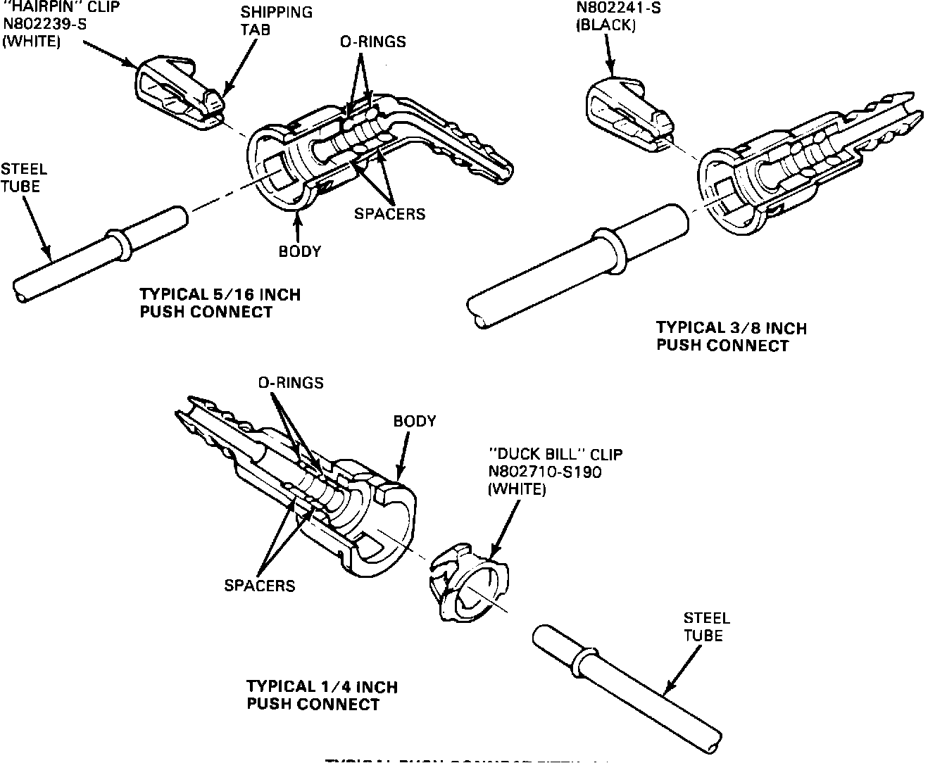
Refer to Figure 24 for an illustration of typical push connect fittings.
PART NUMBER PART NAME CLASS
N802239-S Retainer - 5/16 BG
Hairpin (White)
N802241-S Retainer - 3/8 BG
Hairpin (Black)
N802710-S190 Retainer - 1/4 BG
Duck Bill (White)
OTHER APPLICABLE ARTICLES: 85-6-19
Supersedes: 85-4-38
WARRANTY STATUS: Reimbursable within the provisions of the Warranty and Policy Manual.
OPERATION: 9999A
TIME: 0.3 Hr. DLR. CODING: Basic Part No. 9291 - Code: 73