Fuel Delivery and Air Induction: Description and Operation
Fig. 1 Front view of fuel charging assembly:
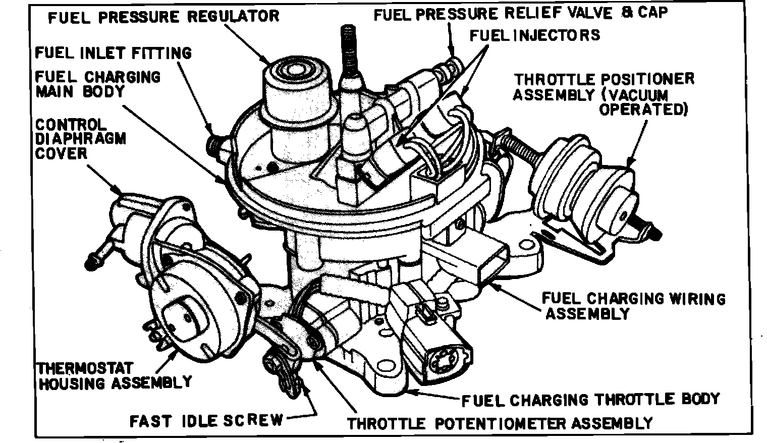
Front view of fuel charging assembly (Vacuum Operated)
Fig. 2 Rear view of fuel charging assembly:
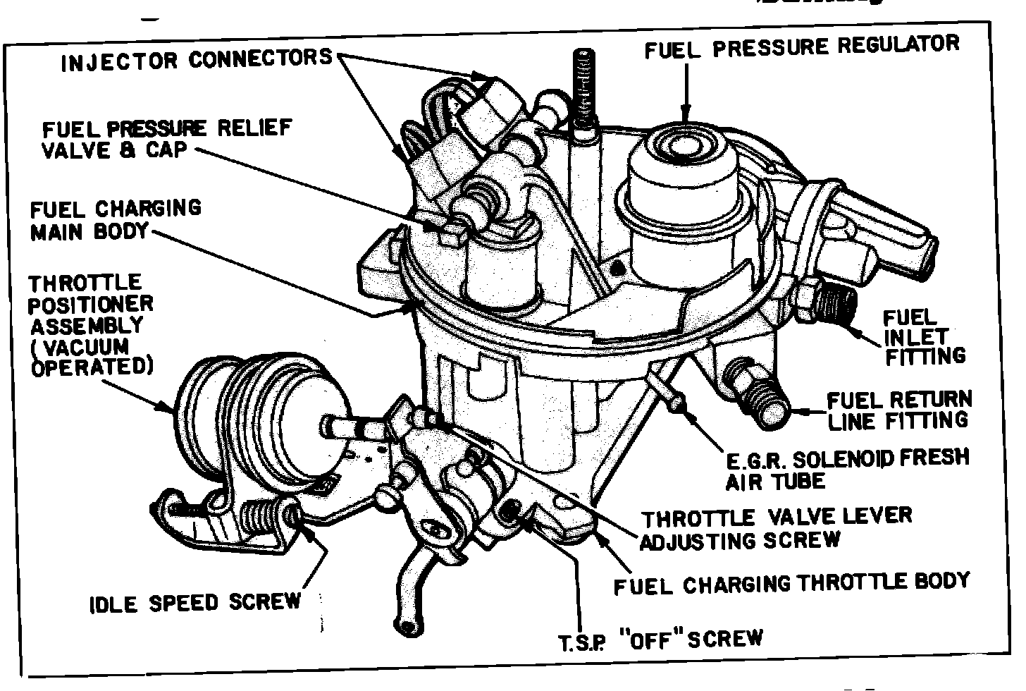
Rear view of fuel charging assembly (Vacuum Operated)
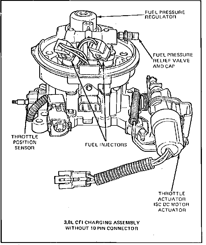
Front view of fuel charging assembly (Electrically Operated)
Fig. 3 Typical CFI fuel system:
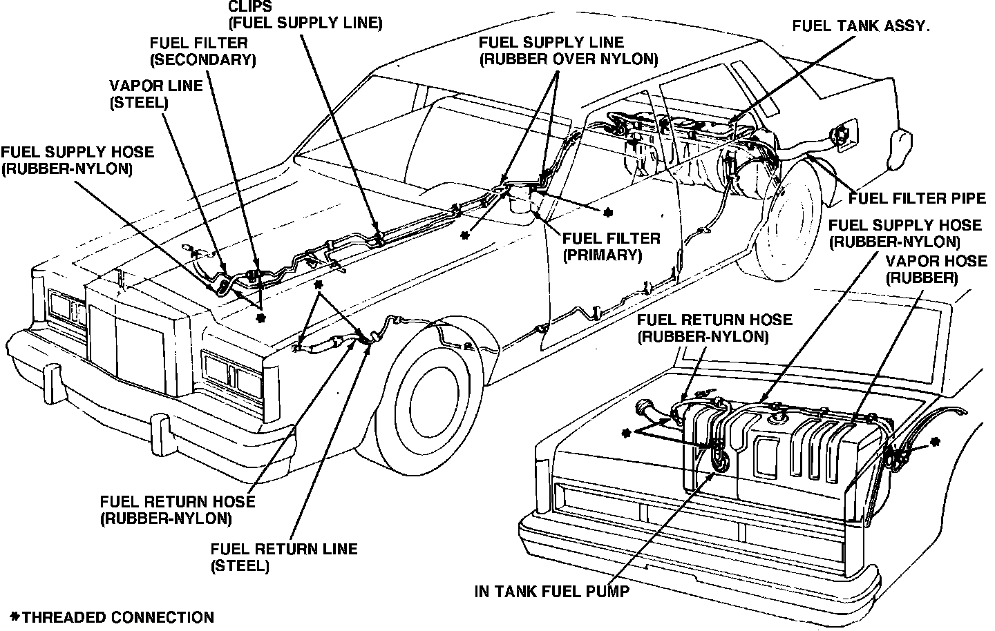
This system is a single point, pulse timed modulated injection system and uses a fuel charging assembly instead of a carburetor. The fuel charging assembly contains two injectors, a fuel pressure regulator and a throttle body. Fuel is metered into the intake air stream according to engine demands by the two injectors.
An in-tank high pressure fuel pump supplies the fuel to the system. The fuel is filtered and sent to the air throttle where the regulator maintains fuel pressure at a constant pressure. Excess fuel supplied by the pump but not used by the engine, is returned to the fuel tank by a fuel return line, Fig. 3.
This system consists of the following four sub-systems: 1) Fuel Delivery, 2) Air and Fuel Control, 3) Engine Sensors and 4) Electronic Control Unit (ECU).