Spark Shorting Plug - Location Correction
91ford13
Article No.
91-5B-29
03/22/91
ELECTRICAL/VACUUM TROUBLESHOOTING MANUAL - 1988 - PAGES 34 AND 159 - LOCATION OF SPARK OUTPUT (SPOUT) SHORTING PLUG REVISED
LIGHT TRUCK: 1988 AEROSTAR
ISSUE: The Spark Output (Spout) Shorting Plug is located in the left fender apron near the VIP test connector. The plug is incorrectly shown as being located in the engine compartment near the distributor on Page 34 and Page 159 of the 1988 Aerostar Electrical/Vacuum Troubleshooting Manual.
ACTION: Refer to the pages following this TSB article for the correct illustration and listing of Electronic Engine Control component locations.
OTHER APPLICABLE ARTICLES: NONE
WARRANTY STATUS: INFORMATION ONLY
OASIS CODES: 290000
1988 ELECTRONIC ENGINE CONTROL 33
The manifold absolute pressure (MAP) sensor supplies the ECA with manifold absolute pressure readings to indicate engine load conditions. The MAP sensor also signals barometric pressure conditions (changes in altitude) with ignition key On and engine Off and updates this information during wideopen throttle conditions.
The heated exhaust gas oxygen (HEGO) sensor generates a voltage signal which signals the oxygen content of the exhaust gases to the ECA.
The power steering pressure switch (PSPS) opens when power steering pressure exceeds a specified pressure. This signals the ECA to increase engine idle rpm to compensate for added load to the engine.
An input is provided from the stoplamps. This input is supplied by the brake on/off (BOO) sensor. When the brakes are applied, the ECA will disengage the converter clutch override (CCO) solenoid, disengaging the locking torque converter. (A4LD automatic transmission only.)
A vehicle speed sensor (VSS) signals the ECA with vehicle speed. The ECA will use this information for idle speed stability, air/fuel calibrations and vehicle speed control.
A profile ignition pickup (PIP) signal is received through circuit 349 (dark blue wire) to pin 56 of the ECA. This signal supplies the ECA with crankshaft position and engine rpm. The ECA uses this information for fuel control, ignition timing, and other various engine functions.
A/C signal - a signal is received from the A/C system that informs the ECA when the A/C clutch has been turned on. This informs the ECA that during periods of wide-open throttle acceleration the A/C compressor needs to be turned off.
ECA OUTPUTS
The converter clutch override (CCO) solenoid is used on vehicles equipped with the A4LD automatic transmission. The solenoid is energized by the ECA to allow the torque converter to lock up, improving fuel economy. The actual lockup is controlled by the transmission.
The 3-4/4-3 shift solenoid shifts the transmission into and out of overdrive based on engine load and road speed.
The throttle air bypass valve solenoid is used by the ECA to control engine idle speed, and acts as an electronic dashpot during periods of deceleration.
The fuel injectors are a normally closed, electromechanical device which meters and atomizes fuel. Since the injector flow orifice is fixed, and the fuel supply is regulated, fuel flow to the engine is controlled by how long the solenoid is energized by the ECA.
The canister purge (CANP) solenoid is used to control the flow of fuel vapors from the carbon canister to the intake manifold.
TROUBLESHOOTING HINTS
When diagnosing problems with the EEC system you must refer to the Engine/Emissions Diagnosis Manual, Volume H for the correct procedures.
Figure 1 - RH SIDE 3.0L EFI ENGINE:
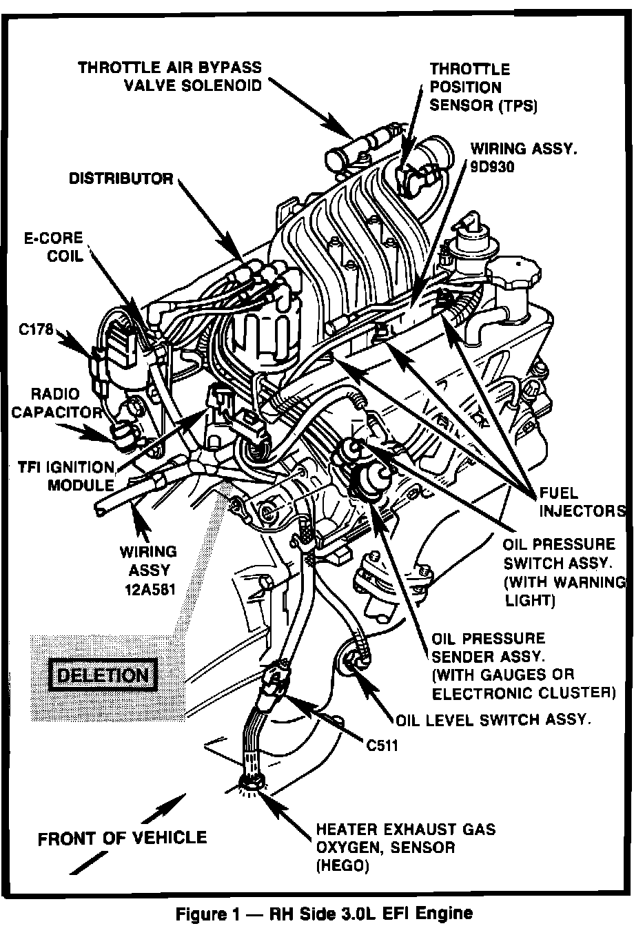
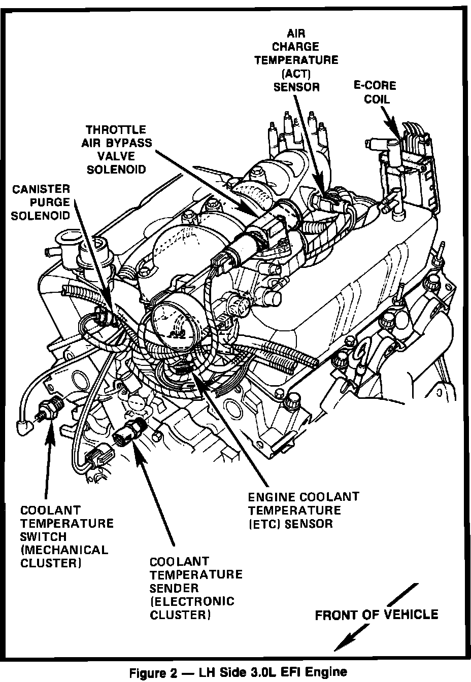
Figure 2 - LH SIDE 3.0L EFI ENGINE:
34 ELECTRONIC ENGINE CONTROL 1988
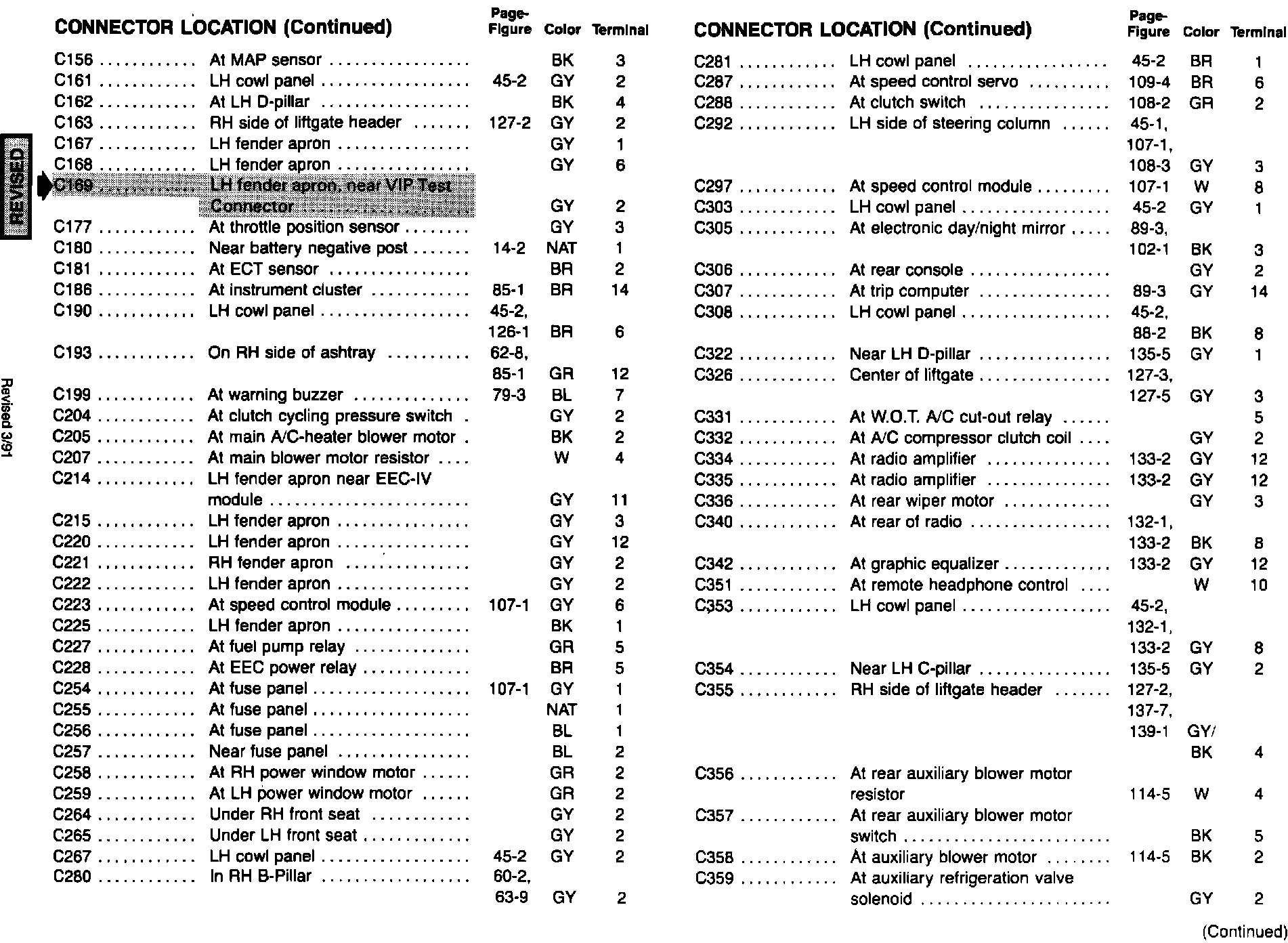
LOCATION INDEX 1988 159

160 1988 LOCATION INDEX