Assembly
1. Place input shaft and synchronizer ring assembly over tapered roller bearings on input end of mainshaft.2. Place mainshaft and input shaft on gear pack holding fixture, tool No. T87T-7025-HH or equivalent.
Meshing Mainshaft And Output Shaft:
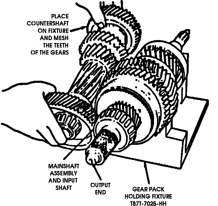
3. Place countershaft on fixture, then mesh gears of two shafts.
4. Place three shift rails and fork assemblies into shift rod support, tool No. T87T-7025-JH or equivalent in their original position.
5. Position three shift rail assemblies together with the shift rod support tool and interlock so that the shift forks engage in the correct mainshaft sliding sleeves.
6. Place shift interlock on three gearshift rails, then engage it in interlock grooves in 5th/reverse upper rail.
7. If equipped slide speedometer worm gear onto mainshaft until it seats against stop on mainshaft.
8. Secure rear cover into bench mounted holding fixture, mainshaft and countershaft.
Positioning Gear Pack For Installation:
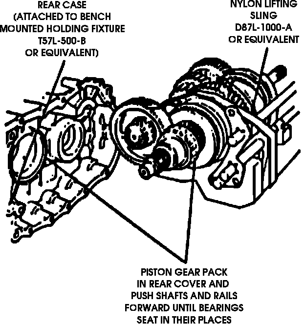
9. Position gear pack into rear cover and push shafts and rails forward until bearings seat in their housing outer races and gearshift rails slide into their retaining holes in housing.
10. Rotate gear pack and rear case upwards 90° in vertical position with the input shaft pointing upwards.
11. If equipped slide output flange onto the output end of mainshaft until it seats against its stop. Screw hex nut onto shaft until finger tight.
NOTE: Use care to ensure mainshaft bearing is not pushed off its race when flange is installed.
12. Remove shift rod support tool from ends of shift rails.
13. Remove strap, then the gear pack holding fixture from mainshaft and countershaft.
14. Attach three cap screws that secure shift interlock to rear transmission housing. Torque cap screw to 7 ft lbs (9 Nm), ensuring interlock moves freely.
15. Engage teeth of reverse idler gear with reverse gear on mainshaft, then slide reverse idler gear shaft downward through bearings and into rear case.
16. Align lower of two threaded holes in shaft with bore with rear case.
17. Place a ``Usit'' (positive engagement retaining ring) on capscrew, then insert screw through bore in housing into shaft. Finger tighten screw.
18. Insert center shift rail and finger assembly into its bore in rear case, then the magnet into recess in housing.
19. If necessary, perform adjustment procedures, then apply a suitable sealant to rear case. If front case, rear case, countershaft mainshaft input shaft, or any bearing required replacement, tapered roller bearing adjustment is required.
NOTE: Do not use a silicone type sealant.
20. Push three shift rail detents back into their holes in front case, using care to ensure shift rail detents do not obstruct entry of shift rails.
21. Carefully place from case over shafts and gearshift rails until it rests on its mating surface of rear case. If necessary to facilitate installation of front case, push central shift rail inward to clear inner surfaces of front case.
22. Drive in two dowels that align rear case and front case, then insert and finger tighten two hex screws.
23. Insert and finger tighten two additional hex screws into rear bores, then adjust main and input shaft preload.
24. Place a Usit ring (positive engagement retaining ring) on reverse idler shaft retaining capscrews, then insert screws through bores in front and rear cases. Torque screw to 16 ft lbs (21 Nm).
25. Manually push sealing covers into capscrews until they are flush with surface of screw head.
CAUTION: Do not hammer covers into position.
26. Rotate transmission, input shaft down, then install speedometer drive gear on mainshaft.
Installing Rear oil Seal:
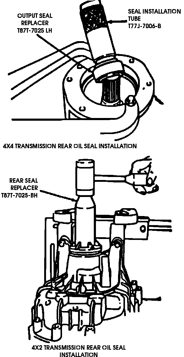
27. Remove output flange to mainshaft hex nut, then the flange from shaft. Position output shaft seal on output shaft seal replacer tool No. T87T-70925-BH or equivalent, then place seal and tool in opening in rear case. Using a suitable mallet, gently tap seal in until it seats in opening. Apply a suitable liquid soap solution around circumference to minimize friction.
28. Reinstall output flange on output shaft. Install companion flange holder tool No. T78P-4851-A, then the hex nut onto mainshaft, using locknut socket tool No. T87T-7025-AH. Torque nut to 184 ft lbs (248 Nm).
29. Secure locknut by bending tab on nut into mainshaft.
30. Install new gaskets and PTO covers over openings in front case, then insert attaching screws and torque to 28 ft lbs (37 Nm).
31. Position 5th/reverse gear interlock plate into its installed position, then place gasket over shift tower mating surface in front case.
32. Ensure stop plate moves freely and no interference from gasket is present. Use care that interlock plate of spring does not drop into front case.
33. Check interlock plate compression spring.
Installing Interlock Plate:
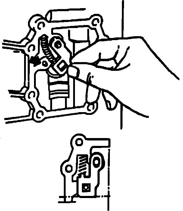
34. Place spring above nose in interlock plate, then move both parts into their installed positions. Ensure interlock function between 5th gear and reverse gear operates properly.
35. Install shift tower assembly, ensuring nose on gearshift finger points towards interlock plate.
36. Install spring washers, then torque screws to 18 ft lbs (24 Nm).
37. Check operation of interlock. Shift lever cannot be shifted between 5th and reverse if interlock is properly installed.
NOTE: Do not force lever to shift into reverse.
Installing Compression Spring:
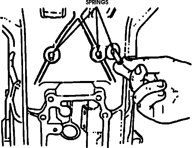
38. Check unloaded length of springs (1.736 inch), then install compression springs over each detent ball as shown.
39. Install cap in each bore in front case where detents, bolts and springs were installed. Drive each cap in until it seats 3/64 inch below surface of housing. Deeper installation will cause high shift efforts.
40. Install back-up lamp switch with new seal, then torque to 15 ft lbs (20 Nm).