Assembly
Transmission
Assembly
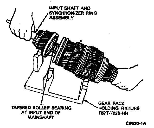
1. Place the input shaft and synchronizer ring assembly over the tapered roller bearing on the input end of the mainshaft.
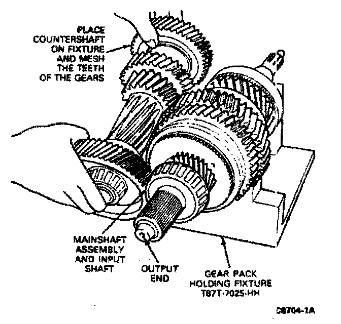
2. Place the mainshaft and input shaft on the Gear Pack Holding Fixture, T87T-7025-HH or equivalent. Place the countershaft on the fixture and mesh the gears of the two shafts.
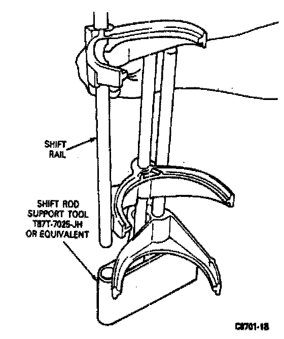
3. Place the three shift rails and fork assemblies into the Shift Rod Support Tool T87T-7025-JH or equivalent in the position from which they were removed during disassembly.
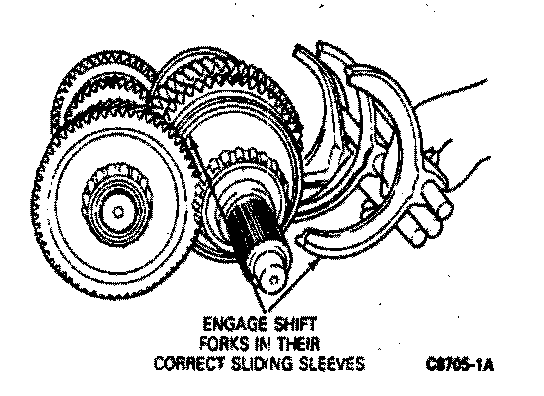
4. Position the three shift rail assemblies together with the shift rod support tool and interlock so that the shift forks engage in the correct mainshaft sliding sleeves.
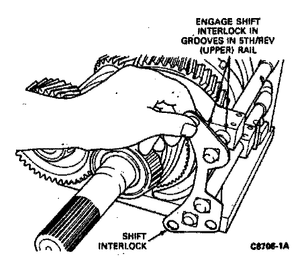
5. Place the shift interlock on the three gearshift rails and engage it in the interlock grooves in the 5th-reverse (upper) tail.
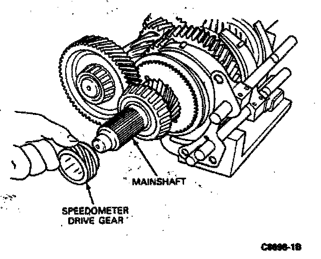
6. If equipped, slide the speedometer worm gear onto the mainshaft until it seats against the stop on the mainshaft.
Note: Ensure speedometer gear is installed with metal spacer towards bearing.
7. Secure the rear case into the bench mounted holding fixture T57L-500-B or equivalent.
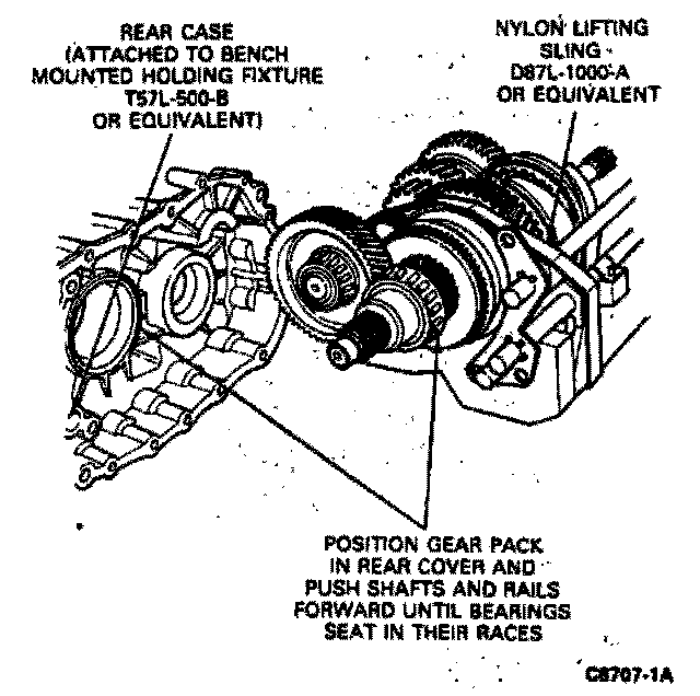
8. Position Nylon Lifting Sling, D87L-1000-A or equivalent around the shift rails, the holding fixture and the mainshaft and countershaft. Position the gear pack into the rear case and push the shafts and rails forward until the bearings sear in their outer races in the housing and the gearshift rails slide into their retaining holes in the housing.
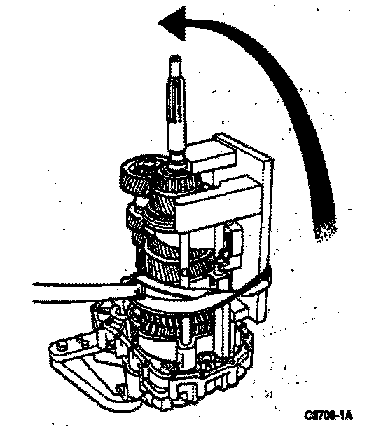
9. Rotate the gear pack and rear case upwards 90 degrees so it is vertical position with the input shaft pointing upwards.
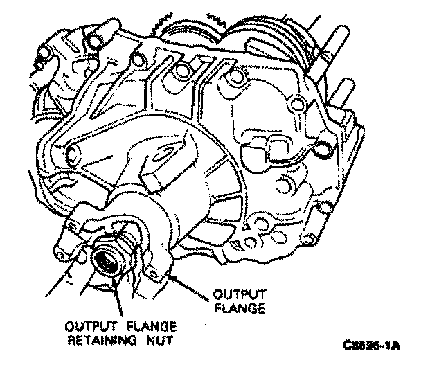
10. If equipped, slide the output flange onto the output end of the mainshaft until it seats against its stop. Screw the hex nut onto the shaft until it is finger-tight.
Caution: Use care to ensure that the mainshaft bearing is not pushed off its races when the flange is installed.
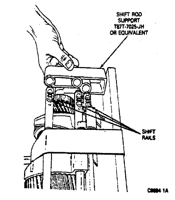
11. Remove the shift rod support tool from the ends of the shift rails.
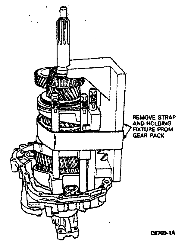
12. Remove the strap and remove the gear pack holding fixture from the mainshaft and countershaft.
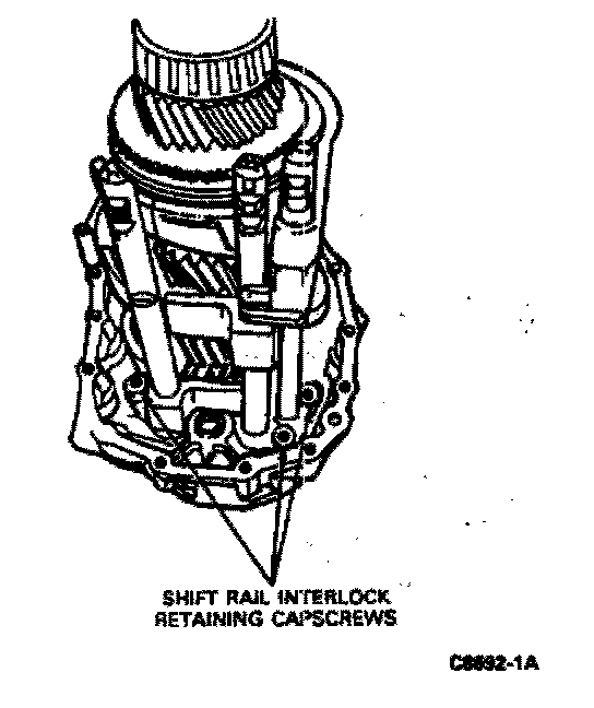
13. Attach the three cap screws that secure the shift interlock to the rear transmission housing. Tighten them to 10 Nm (7 ft lbs). Be sure that the interlock moves freely after tightening the screws.
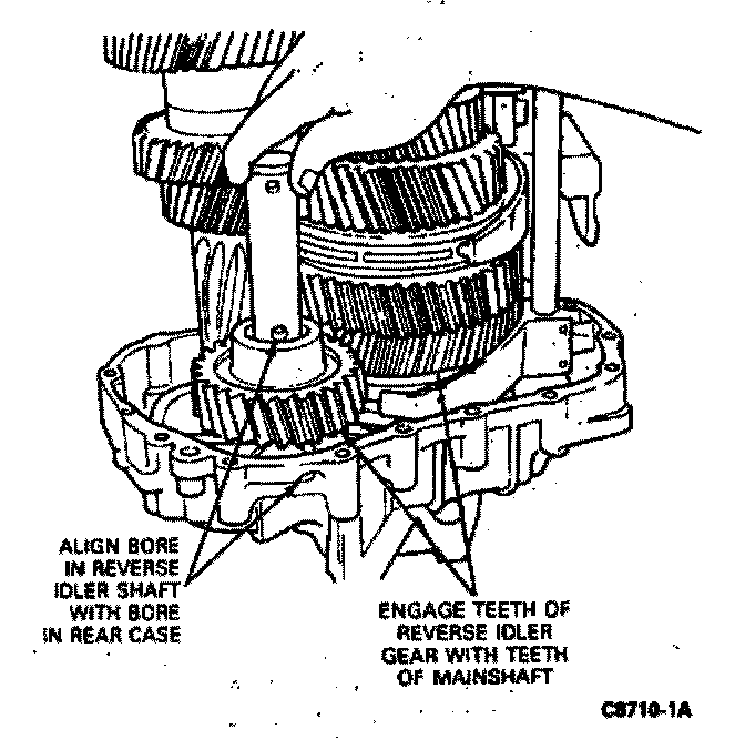
14. Engage the teeth of the reverse idler gear with the reverse gear on the mainshaft. Slide the reverse idler shaft downward through the bearings and into the rear case. align the lower of the two threaded holes in the shaft with the bore in the rear case. Place a sealing ring on the capscrew and attach the screw through the bore in the housing into the shaft. Tighten the screw finger-tight.
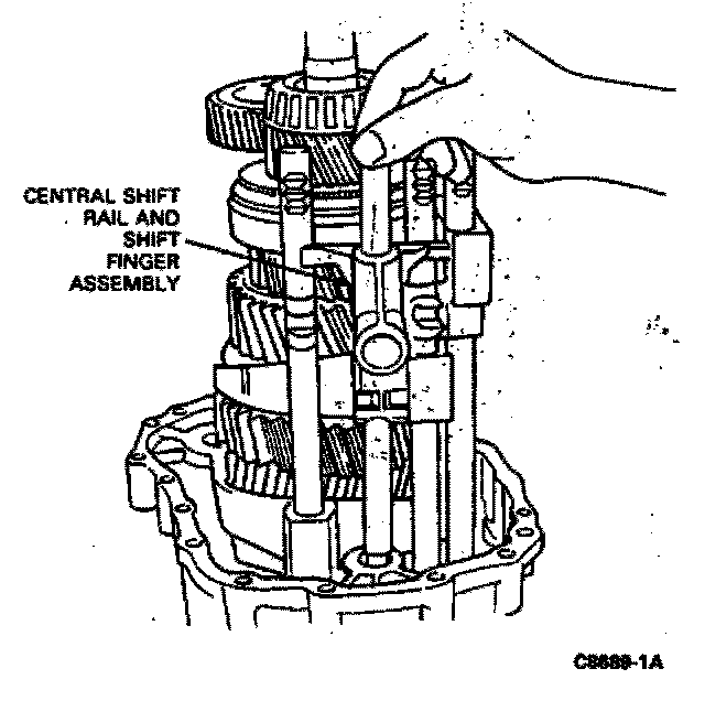
15. Insert the central shift rail and finer assembly into its bore in the rear case.
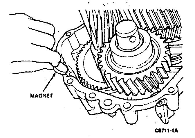
16. If the magnet was removed during disassembly, insert it in the recess in the housing.
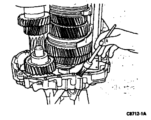
17. If the tapered roller bearings on the mainshaft, input shaft or countershaft do not have to be adjusted, thinly coat the sealing surface of the rear case with Gasket Maker E2AZ-19562-B (ESE-M4G234-A2) or equivalent.
Note: Do not wait longer than ten minutes to tighten all 17 bolts, due to the rapid curing time of the sealant.
Caution: Do not use silicone Sealing Compound or equivalent.
Note: The tapered roller bearings preload should be adjusted if either the front or rear cases, countershaft, mainshaft, input shaft, or a bearing has been replaced. If the tapered roller bearings on the mainshaft, input shaft, or countershaft have to be adjusted, do not apply the sealant at this time.
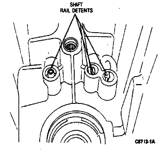
18. If removed, push the three shift rail detents back into their holes in the front case.
Caution: Use care to ensure that the shift rail detents do not obstruct entry of the shift rails.
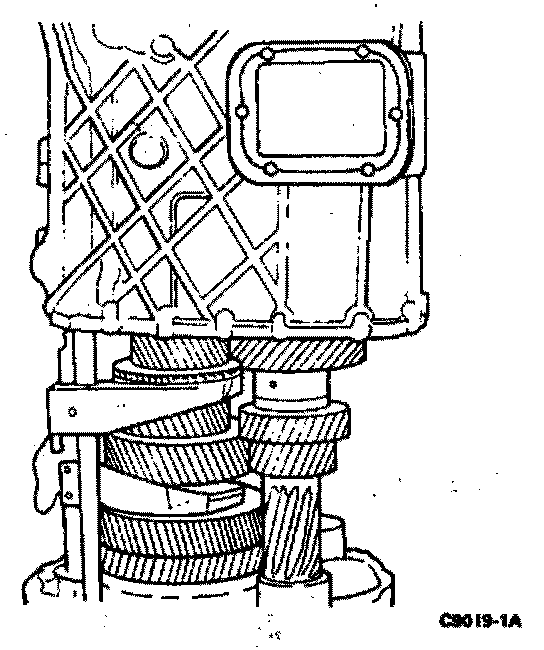
19. Carefully place the front case over the shafts and gearshift rails until it rests on its mating surface on the rear case. It may be necessary to push the central shift rail inward to clear the inner surfaces of the front case.
Caution: Be careful that the input shaft does not damage the front seal. Also be careful that the shim pack oil baffle is not bent when the case is positioned over the input shaft.
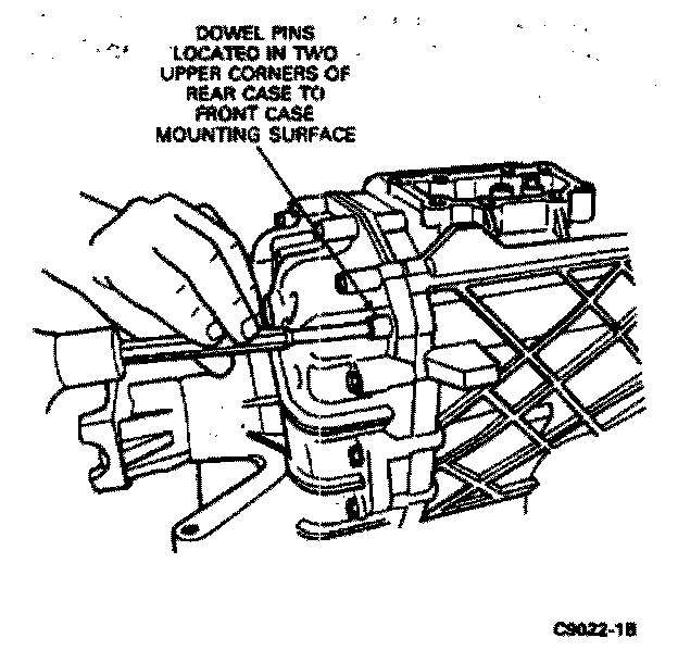
20. Drive in the two dowels that align the rear case and the front case. Next, insert two hex screws and tighten them finger-tight.
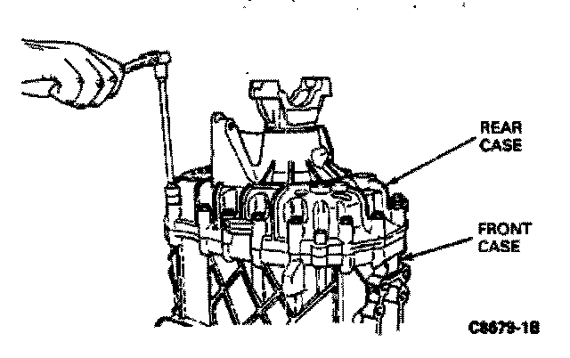
21. Screw two additional hex screws into the rear case bores near the shafts finger-tight.
Note: If it is not necessary to adjust the mainshaft/input shaft preload. Install all of the hex screws that attach the two cases and tighten to 22 Nm (16 ft-lb).
Caution: Adjustment of tapered roller bearing preload is necessary if either the front or rear cases, countershaft, mainshaft or input shaft has been replaced, or if a tapered roller bearing on either shaft has been replaced.
22. Fit sealing ring to the remaining reverse idler shaft retaining capscrews. Install the screw into the bore in the front case and tighten both capscrews to 22 Nm (16 ft-lb). With a screwdriver push caps into the capscrews until they are flush with the surface of the screw head.
Note: The rear case capscrew was installed finger-tight in step fourteen.
Caution: Use hand pressure for screwdriver only, do not hammer the caps into position.
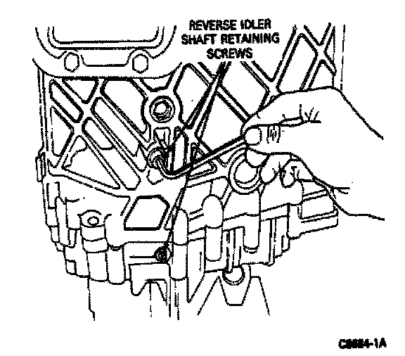
23. Rotate the transmission so that input shaft is pointing down.
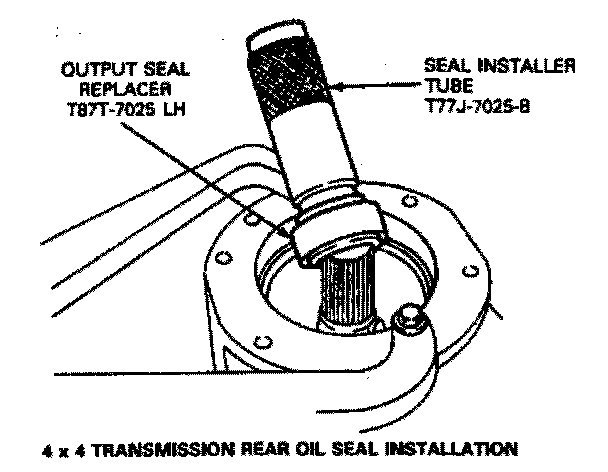
24. On 4x2 transmissions, remove the hex nut that secures the output flange to the mainshaft, then remove the flange from the shaft. Position the output shaft seal on Output Seal Replacer T87T-7025-BH or equivalent and position the seal and tool in the opening in the rear case. Using a sof thammer gently tap the seal in until seals in the opening. Apply a little liquid soap around the circumference to minimize friction.
4x4 Transmission Rear Oil Seal Installation:
4x2 Transmission Rear Oil Seal Installation:
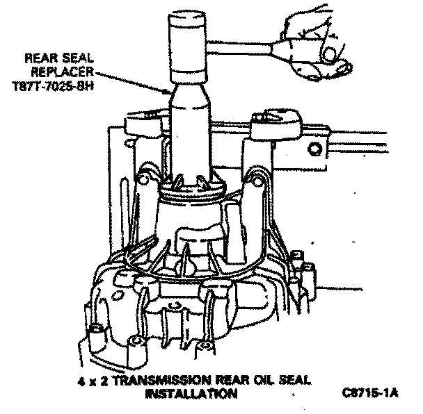
25. On 4x4 transmissions, Output Seal Replacer T87T-7025-LH or equivalent and Seal Installer Tube T77J-7025-B or equivalent to install the output shaft oil seal. Gently tap on tube with a soft hammer until tool seats against its stop.
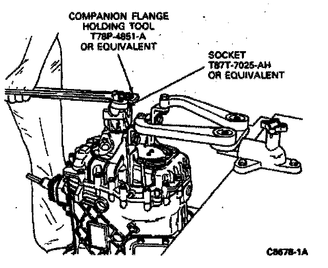
26. On 4x2 transmissions, reinstall the output flange on the output shaft. Install Companion Flange Holder T78P-4851-A. Install a new hex nut onto the mainshaft using locknut socket Tool T87T-7025-AH. Tighten the nut to 250 Nm (184 ft-lbs).
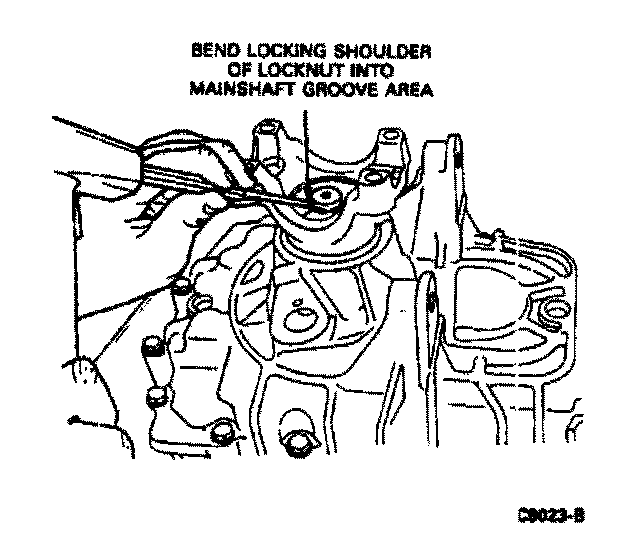
27. Secure the locknut by bending the locking shoulder of the nut into the mainshaft groove.
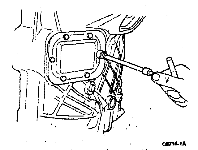
28. If required, install new gaskets and PTO covers over the openings in the front case using the original attaching screws which have self sealing threads and tighten to 38 Nm (28 ft-lbs).
29. Position the 5th-reverse gear interlock plate into its installed position as shown in the illustration. Place the gasket over the shift tower mating surface in the front case.
Note: Make sure that the stop plate moves freely and that the gasket does not interfere with it. The interlock plate must be in a position which is lower than the gasket so that plate may move freely.
Note: Use care to ensure that the interlock plate or spring do not drop into the front case.
30. Check the interlock plate compression spring against Spring Specifications to be sure that its unloaded length is satisfactory.
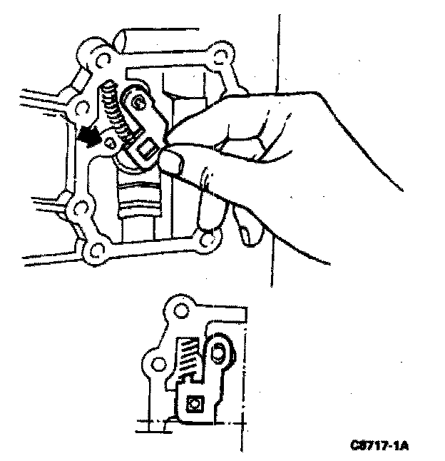
31. Place the spring above the nose in the interlock plate and move both parts into their installed positions.
Caution: The procedure must be followed exactly to ensure that the interlock function between fifth gear and reverse gear operates properly.
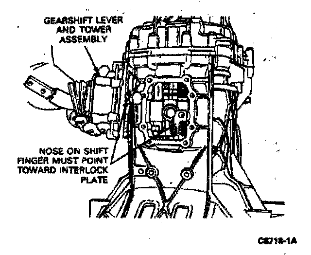
32. Install the shift tower assembly. The nose on the gearshift finger must point toward the interlock plate. Install spring washers and tighten screws to 22 Nm (16 ft-lbs).
33. Check the functioning of the interlock. The shift lever cannot be shifted between fifth and reverse if the interlock was properly installed.
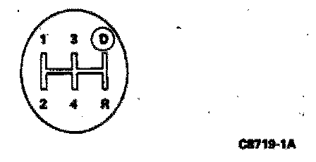
Caution: Do not force the lever to shift into reverse. Damage to the interlock components could occur.
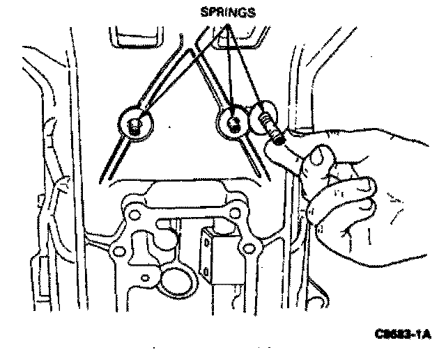
34. A compression spring is installed into each of the three detent bolts. The positions are shown in the illustration. Before installing the springs, check that their unloaded length is 44.1mm (1.736 inch).
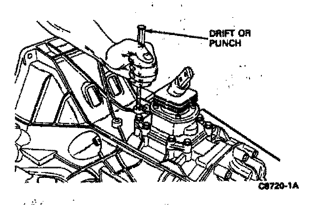
35. Install a new sealing cap in each bore in the front case where the detents, bolts and springs were installed. Use a suitable drift or punch to drive each cap in until seats 1mm (3/64 inch) below the surface of the housing.
Note: Deeper installation will cause high shift efforts.
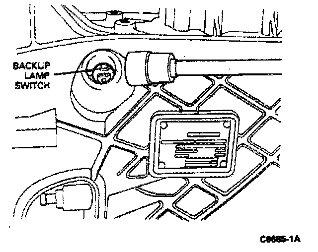
36. If removed install the back-up lamp switch with a new sealing ring into its mounting boss on the side of the front case near the transmission nameplate. Tighten the switch to 20Nm (15 ft-lbs).