Disassembly
Transmission
Disassembly
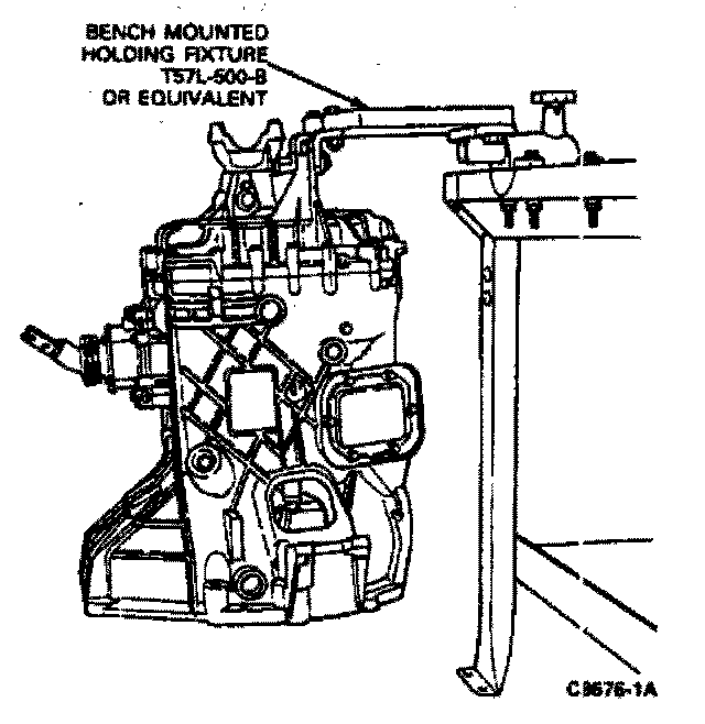
1. Attach the transmission to the Bench Mounted Holding Fixture T57L-500-B or equivalent. Place the transmission in a vertical position with the front case pointing downward.
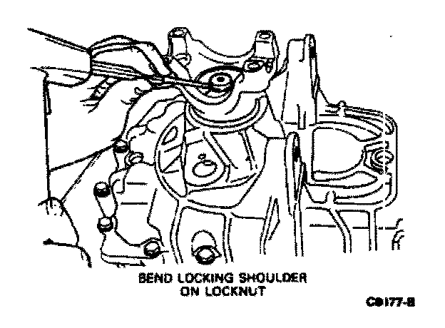
2. Using a chisel, bend back the locking shoulder of the output flange retaining locknut.
3. Attach Companion Flange Holding Tool T78P-4851-A or equivalent to the transmission output flange.
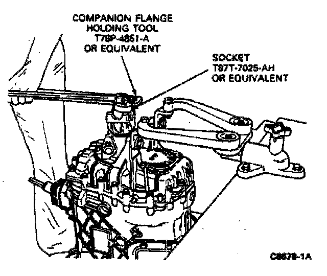
4. Loosen the hex nut that holds the output flange to the mainshaft with Thin-Walled Socket T87T-7025-AH or equivalent. Remove the flange holding tool after loosening the nut.
Caution: Do not remove the hex nut or output flange at this time.
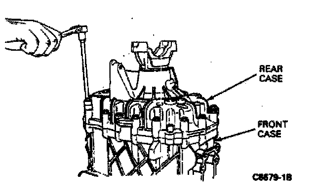
5. Remove 15 of the 17 8mm hex head screws that hold the front and rear cases together. Leave two screws at opposite sides of the case installed.
6. Remove any power take-off equipment installed on the transmission.
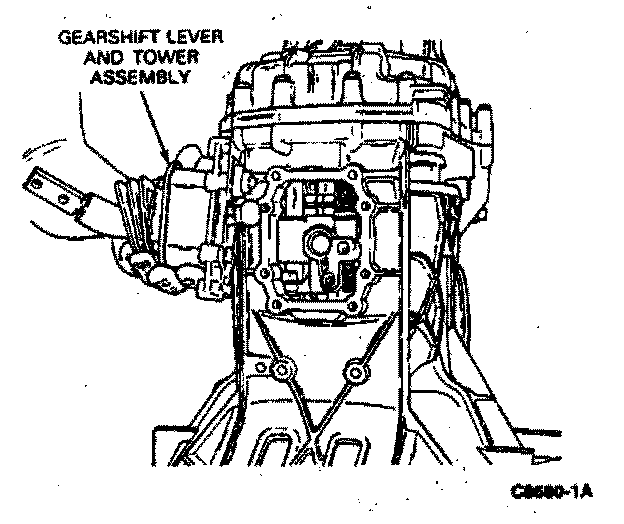
7. Remove the eight 8mm hex bolts that attach the shift tower assembly to the front case. Remove the complete gearshift lever and tower as as assembly. Rotate transmission on holding fixture so that the front case is pointing upward.
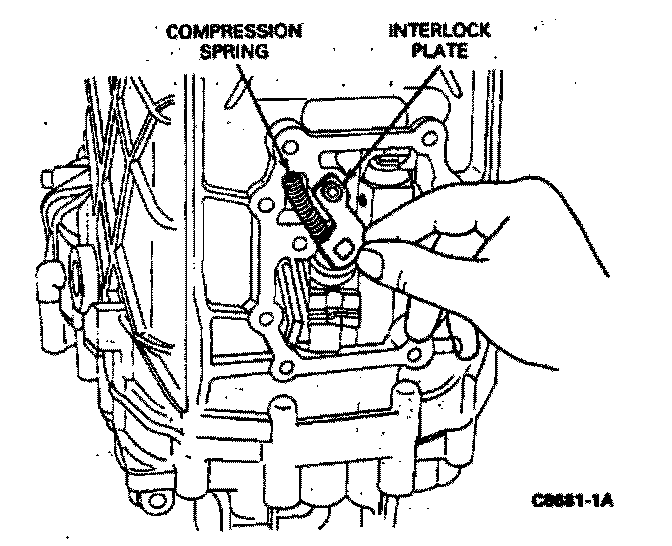
8. Remove the interlock plate and compression spring which serves as a reverse gear interlock.
Caution: Use care to ensure that parts do not inadvertently fall into transmission.
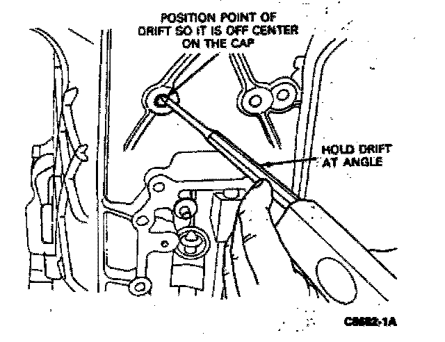
9. Place a drift punch against the dentent bolt sealing cap. Hold the drift at an angle. Position the point of the drift punch so it is off center on the cap. Drive the cap inward until spring pressure against its underside forces the cap out of its hole. Repeat this procedure for the other two detent bolt sealing caps in the front case.
Warning: Cap is under spring pressure. Always wear protective eyeglasses when performing this procedure to ensure that cap does not strike eyes when it is forced out by spring pressure.
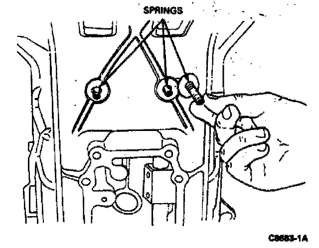
10. Remove the springs that are now protruding from the sealing cap holes.
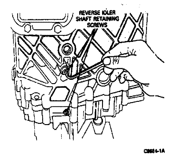
11. Drive out the sealing caps for the two reverse idler shaft cap screws. Remove the reverse idler shaft cap screws.
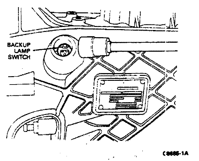
12. If required, remove the back-up lamp switch, located above and slightly forward of the transmission nameplate. Remove the back-up lamp switch sealing ring.
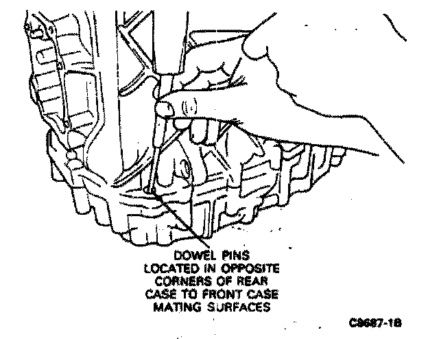
13. Use a suitable punch to remove the two dowel pins located in opposite corners of the rear case to front case mating surfaces. Drive them out toward the rear of the transmission.
14. Remove the two remaining hex bolts from the rear case.
Note: The transmission input shaft is facing upward during this operation.
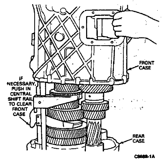
15. Carefully lift the front case off of the rear case. It may be necessary to push the central shift rail inwards to prevent it from "hanging up" on the front case as it is being removed. Use care to ensure that the central shift rail is not lifted off together with the front case.
Caution: The mating surfaces of the two housing assemblies are coated with an adhesive sealing agent. If it is difficult to separate the two housings because of this adhesive, carefully tap the front of the front case with a soft hammer until the bond is loosened. Never use a prying device, such as a screwdriver, or chisel, to force the housing apart. It could damage the surface and cause leaks.
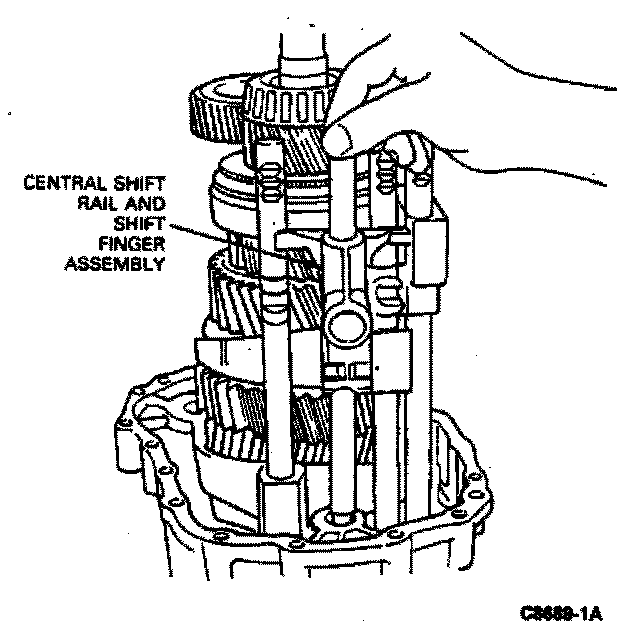
16. Remove the central shift rail and shift finger assembly.
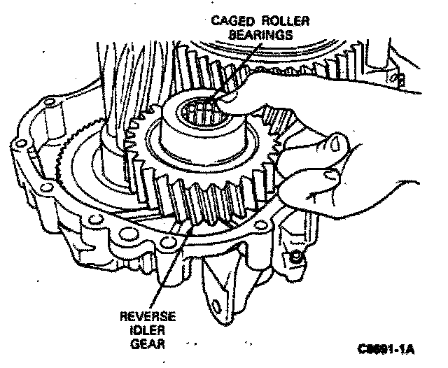
17. Left the shaft out of the reverse idler gear, and remove the gear and two caged roller bearings from the rear case.
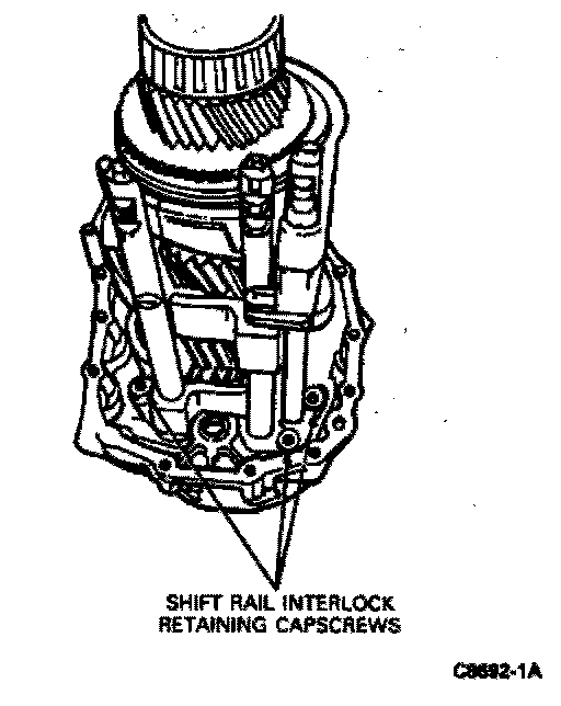
18. Remove the three capscrews that retain the shift interlock to the rear case.
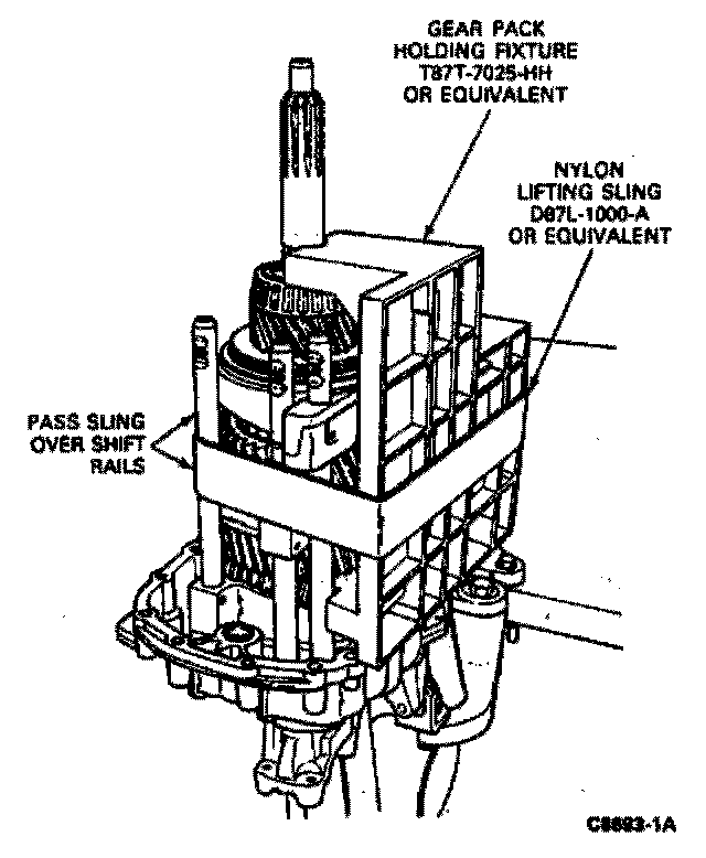
19. With the transmission in a vertical position, use Nylon Lifting Sling D87L-1000-A or equivalent to strap Gear Pack Holding Fixture T87T-7025-HH or equivalent to the mainshaft and output shaft assemblies. Pass the sling over the shift rails.
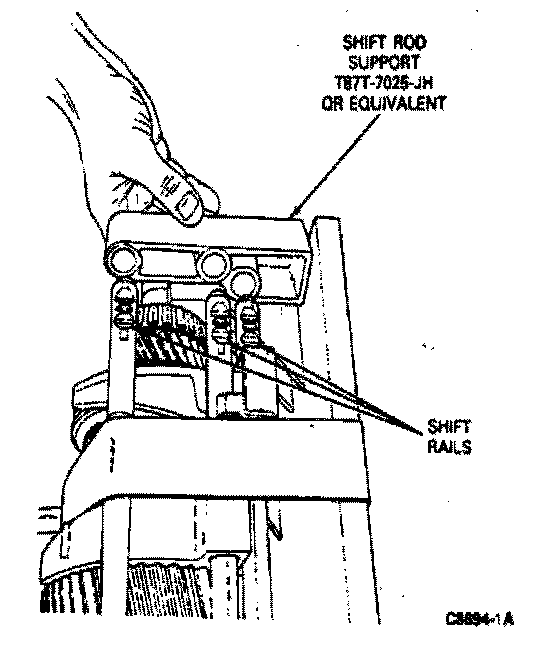
20. Place the Shift Rod Support, T87T-7025-JH or equivalent over the ends of the shift rails.
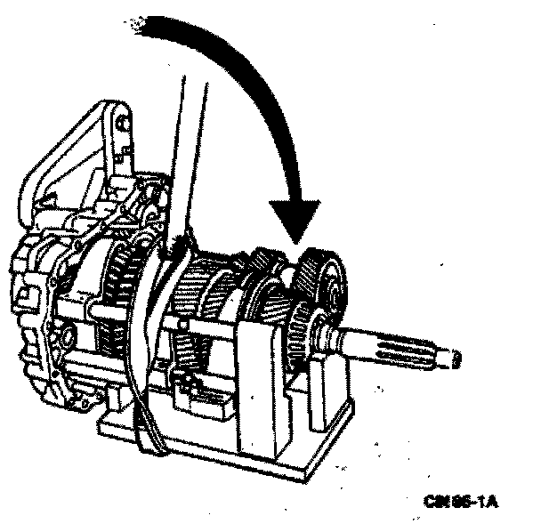
21. Carefully rotate the transmission, together with the gear pack holding fixture, into a horizontal position with the holding fixture beneath the gear pack.
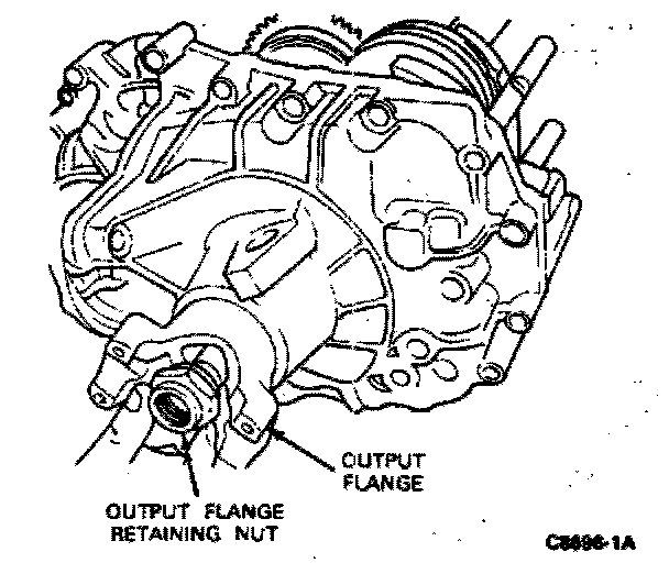
22. Remove the output shaft flange retaining nut from the output shaft. Remove the flange from the output shaft. If the flange is difficult to remove, tap it loose with a hammer.
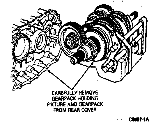
23. Carefully pull the gearpack and shift rails and their holding fixtures forward to dislodge them from the rear case. Place this assembly on a workbench.
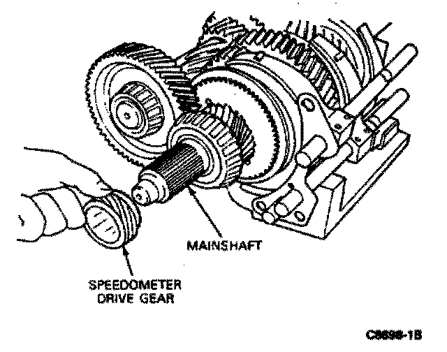
24. If equipped, remove the speedometer drive gear from the mainshaft.
25. Remove the sling from around the shift rails, gearpack, and holding fixture.
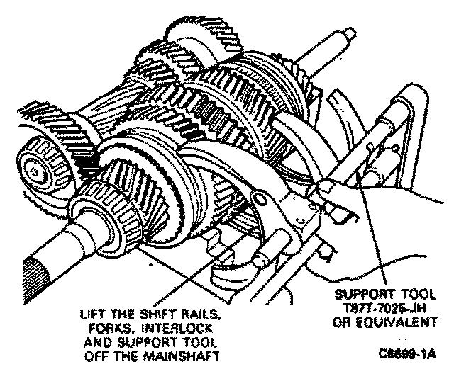
26. Turn the gearshift rails approximately 45 degrees to release them from the shift hubs. Lift the gearshift rails, forks and interlock, together with Support Tool T87T-7025-JH, off the mainshaft.
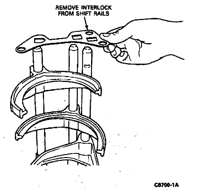
27. Using the shift rod support tool as a base, set the shift rail assembly on a workbench with the shift rails in a vertical position. Remove the interlock.
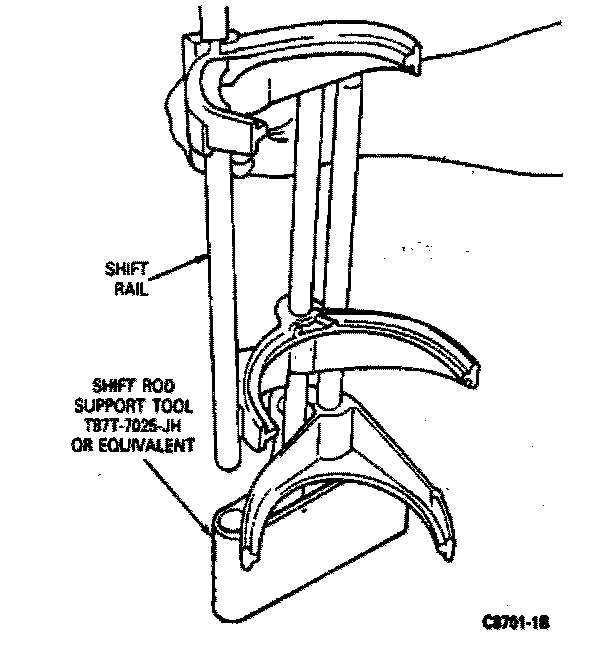
28. Mark each shift fork, shift rail, and position in the holding fixture to make reassembly easier. Lift the shift rails from the support tool.
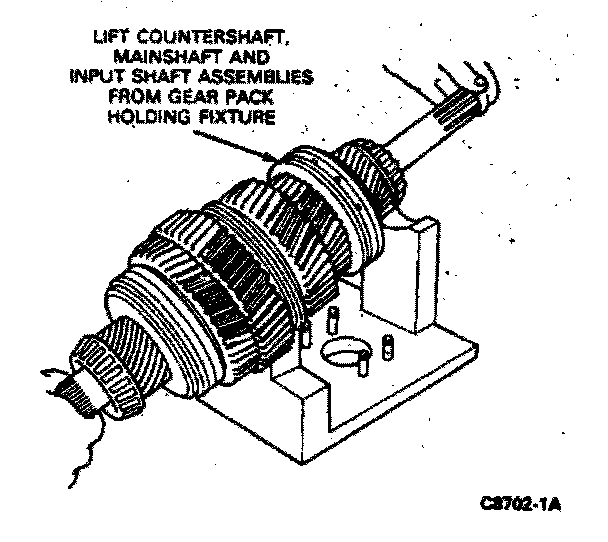
29. Lift the countershaft off the bench stand. Separate the input shaft from the mainshaft. Lift the mainshaft from the stand.
30. Remove the rear cover from the holding fixture.