Intake Manifold: Service and Repair
REMOVAL
1. Disconnect battery ground cable and move out of the way.
2. Drain engine cooling system.
3. Remove air cleaner hoses to throttle body and rocker cover.
4. Carefully relieve fuel pressure at fuel supply manifold schrader valve.
5. Disconnect fuel lines.
6. Mark vacuum line location and remove lines.
7. Disconnect Air Charge Temperature (ACT), Engine Coolant Temperature (ECT), Throttle Position Sensor (TPS), and coolant temperature sender.
8. Remove brace spanning from alternator to throttle body stud.
9. Remove throttle body.
10. Disconnect fuel injector harness stand-offs from inboard rocker cover studs and each injector and remove from engine.
11. Disconnect upper radiator hose from thermostat housing. After loosening retaining clamp. use a twisting motion on hose to loosen from housing.
12. Disconnect heater hoses.
13. Disconnect ECT sensor and coolant temperature sending unit connectors.
14. Mark distributor housing to block, and note rotor position. Remove ignition wires from spark plugs. Remove distributor.
15. Remove ignition coil from intake manifold.
16. Remove rocker arm covers.
17. Loosen retaining nut from cylinder #3 intake valve and rotate rocker arm fulcrum away from valve retainer. Remove pushrod.
18. Remove intake manifold attaching bolts using a torx type socket. Before attempting to remove intake manifold, break the seal between the manifold and the cylinder block. Wedge a large screwdriver between the manifold and the block. Pry downward on the screwdriver using the lug on the water pump as a leverage point. Use care to prevent damage to machined surfaces.
NOTE: Manifold assembly can be removed with fuel supply rails and injectors in place.
INSTALLATION
1. Clean intake manifold gasket surface on cylinder head. Lay a cloth in the tappet valley to catch any gasket particles. After scraping, lift cloth so no gasket material falls into valley holes. Use caution when scraping intake manifold as aluminum gouges easily. Use a suitable solvent to remove old silicone rubber sealer.
Intake Manifold To Cylinder Block Seal:
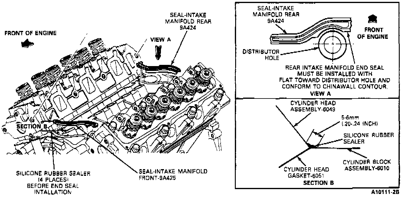
2. Apply Silicone Rubber Sealer D6AZ-19562-AA or BA (ESB-M4G9Z-A) or equivalent to intersection of cylinder block and cylinder head assembly at four corners as shown.
NOTE: When using silicone rubber sealer, assembly must occur within 15 minutes after sealer application. After this time, the sealer may start to set-up, and its sealing effectiveness may be reduced. In high temperature/humidity conditions, RTV will start to "skin over" in approximately 5 minutes.
3. Install front and rear intake manifold seals. Secure with retaining features.
Intake Manifold Gasket:
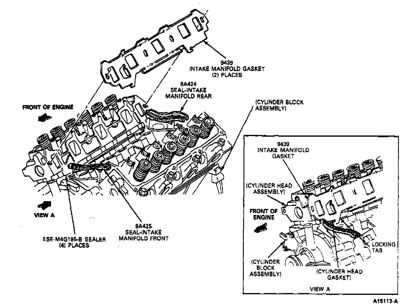
4. Position intake manifold gaskets onto cylinder heads and insert locking tabs on cylinder head gaskets.
Intake Manifold Torque Sequence:
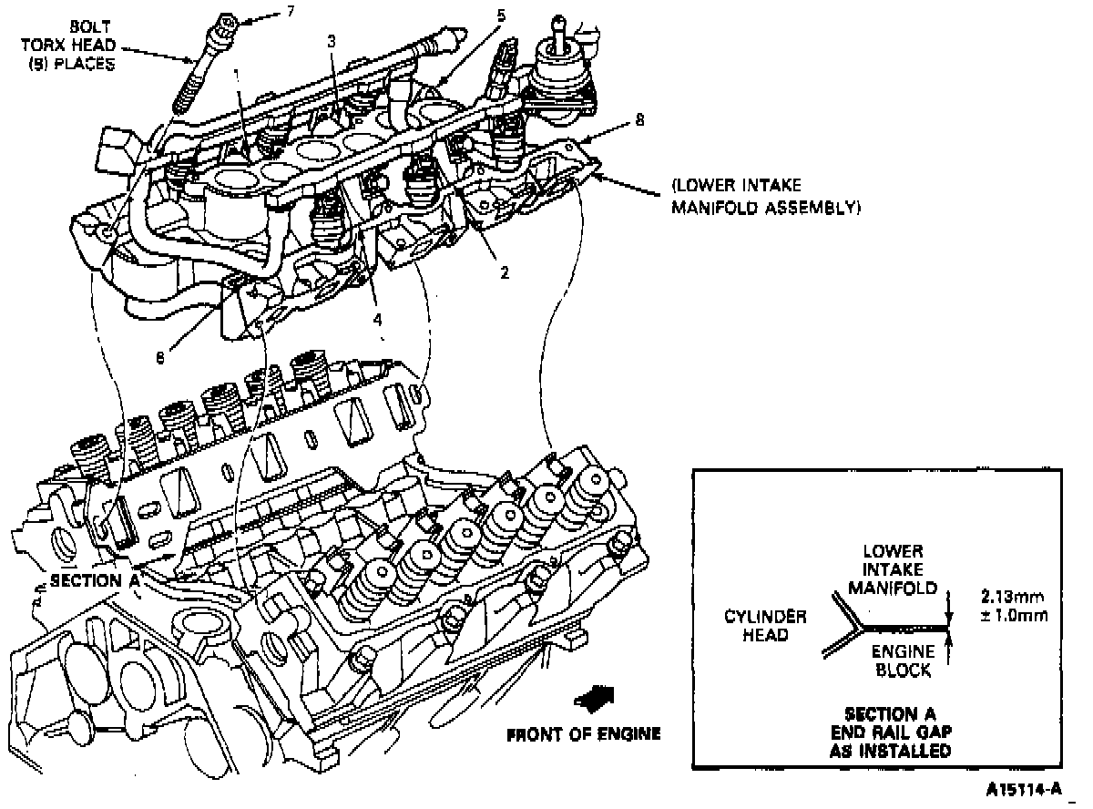
5. Carefully lower intake manifold into position on cylinder block and cylinder heads to prevent disturbing the silicone sealer and causing gasketing voids. Install bolts # 1, 2, 3 and 4 and snug as required. Install remaining bolts and torque in numerical sequence in two steps:
Step 1. tighten bolts to 15 Nm (11 ft lb)
Step 2. tighten bolts to 26 Nm (19 ft lb)
NOTE: Lightly oil all attaching bolt and stud threads before installation.
6. Install thermostat and housing, if removed, with new gasket. Tighten attaching bolts to 25 Nm (19 ft lb).
7. If installing a new manifold, install fuel supply rail and injectors.
8. Install #3 cylinder intake valve pushrod. Apply ESE-M2C39-F oil to pushrod and fulcrum prior to installation. Rotate crankshaft to place lifter on heel or base circle of camshaft. Tighten to 11 Nm (8 ft lb) to seat fulcrum in cylinder head. Final tighten bolt to 32 Nm (24 ft lb).
9. Install rocker covers and tighten bolts to 10-14 Nm (7-10 ft lb).
10. Install fuel injector electrical harness.
Ignition Coil Assembly:
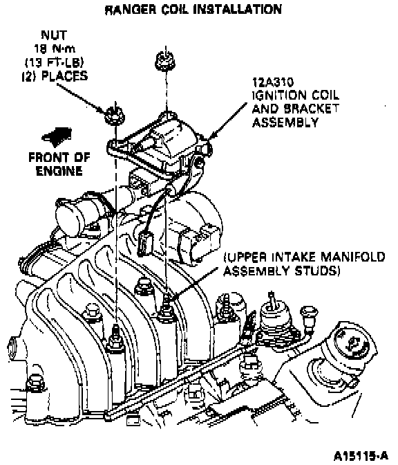
11. Install throttle body assembly and new gasket. Install ignition coil. Tighten retaining nuts to 18 Nm (13 ft lb).
12. Install alternator to throttle body brace. Tighten nuts to 16 Nm (12 ft lb).
13. Connect PCV hose at PCV valve.
14. Connect ECT, ACT, TPS, and coolant temperature sensors.
15. Install distributor and ignition harness and EEC distributor connector.
16. Install coolant hoses. Tighten clamps securely.
17. Connect removed vacuum hoses to their original locations.
18. Connect fuel lines to fuel supply rail.
19. Install fuel line safety clips.
20. Fill and bleed cooling system with specified coolant and proper mixture.
CAUTION: This engine has aluminum components and requires a special corrosion-inhibited coolant formulation to avoid radiator damage.
21. Replace crankcase oil.
NOTE: Engine coolant is corrosive to all engine bearing material. Replacing engine oil after removal of a coolant carrying component precludes failure later.
22. Install air cleaner hose to throttle body and rocker cover.
23. Connect battery ground cable.
24. Start engine and check for coolant, oil, fuel and vacuum leaks.
25. Verify distributor base initial timing.
26. Check, and if necessary, adjust engine idle speed, transmission throttle linkage, and speed control.