Brake Pad: Service and Repair
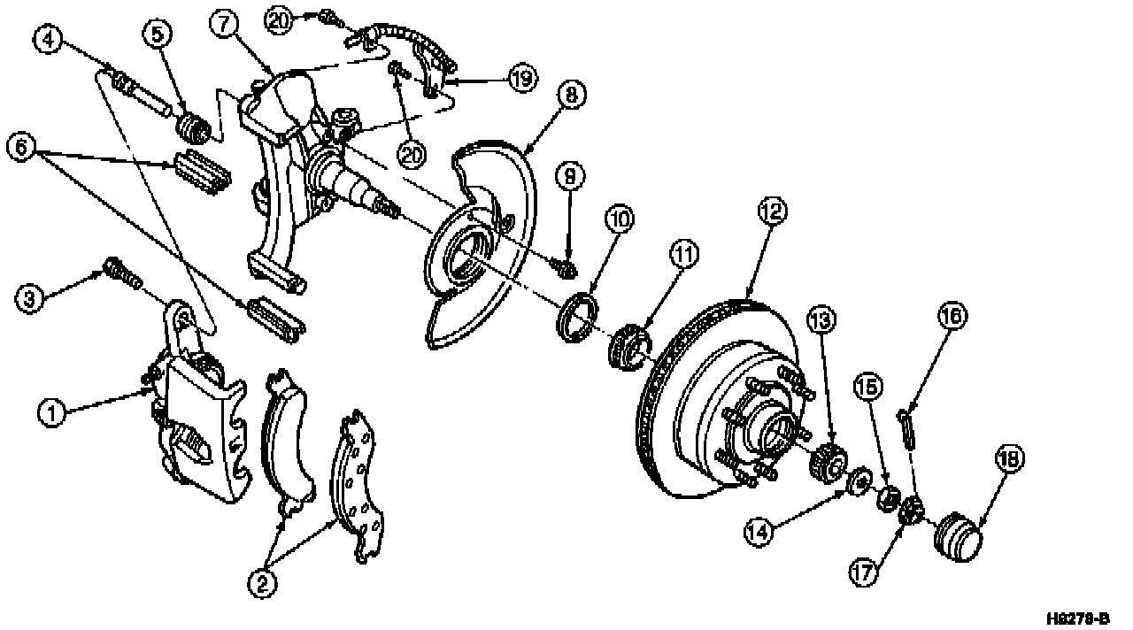
Front Disc Brake Assembly:
ITEM PART DESCRIPTION
NUMBER
1 2B120 Front Disc Brake Caliper
2 2018 Brake Shoe and Lining, Outer
3 N601797-S2 Bolt, Caliper Mount, M12 1.75 x 30
Hex Head Lock
4 2C150 Pin, Caliper Slide
5 -- Boot, Slide Pin
(Part of 2C150)
6 2B164 Disc Brake Pad Anti-Rattle Clip
7 3105 Front Wheel Spindle
8 2K004 Front Disc Brake Rotor Shield
9 N611172-S2 Screw, Self-Tapping, M6 1.0 x 10
(Three Required)
10 1190 Wheel Hub Grease Seal
11 4221 Differential Bearing, Inner
12 1102 Front Disc Brake Hub and Rotor
13 1216 Differential Bearing, Outer
14 1195 Front Wheel Outer Bearing Retainer
Washer
15 374504-S100 Nut, Spindle
16 N642569-S36 Pin, Cotter
17 390622-S Nut Retainer
18 1131 Hub Grease Cap
19 2C204 Front Brake Antilock Sensor
20 N611174-S2 Screw (Two Req'd)
REMOVAL
1. To avoid fluid overflow when the caliper wheel cylinder pistons are pressed into the caliper cylinder bores, siphon or dip part of the brake fluid out of the brake master cylinder reservoir.
NOTE: Discard the removed fluid.
2. Raise the vehicle on a hoist and install safety stands. Remove the wheel and tire.
NOTE: Do not use a screwdriver or similar tool to pry the wheel cylinder piston away from the front disc brake rotor.
Compressing Front Caliper:
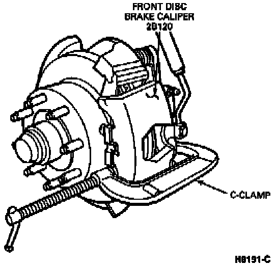
3. Place an appropriate size C-clamp on the front disc brake caliper with end of clamp against caliper and end of screw against outer shoe. Tighten the clamp to bottom the wheel cylinder pistons in the cylinder bores. Remove the C-clamp.
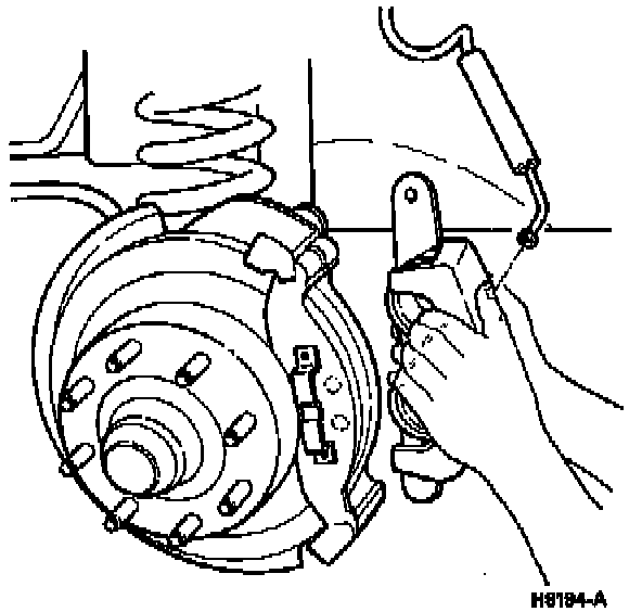
Upper Anchor Bolt Removal:
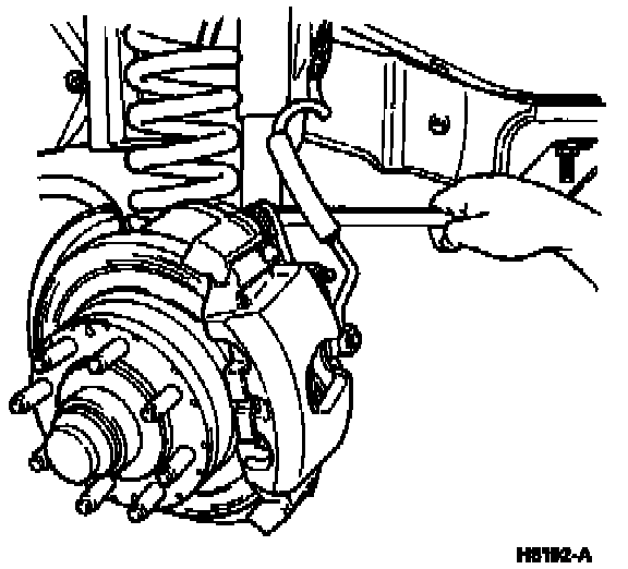
4. Remove the upper anchor bolt only.
NOTE: The front disc brake caliper does not have to be completely detached to remove and install the brake shoes and linings.
Brake Pad Access:
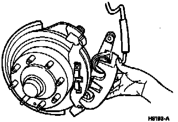
5. Swing the front disc brake caliper down. Remove brake shoes and linings from the front wheel spindle.
Front Caliper Removal:
6. If the front disc brake caliper is to be removed for repair or replacement, disconnect the front brake hose from the front disc brake caliper. Plug the end of the front brake hose to prevent fluid loss and the entry of air into the system. Remove the lower anchor bolt and remove the front disc brake caliper at this time.
7. Inspect the slide pin assemblies for any damage or wear. Replace if necessary, Inspect the rubber boots over the anchor bolts. Replace if torn or deteriorated.
INSTALLATION
1. Install slide pin assemblies. Lubricate slides with Disc Brake Caliper Slide Grease D7AZ-19590-A (ESA-M1C172-A) or equivalent. Position brake shoes and linings onto front wheel spindle. Rotate front disc brake caliper back up into position. If the front disc brake caliper was removed, position it to the front wheel spindle.
2. Install the anchor bolt(s) through front disc brake caliper and front wheel spindle. Tighten bolts to 115-135 Nm (85-100 ft lb).
Caliper Inlet Block:

3. Replace both washers (each side of inlet block). Connect the front brake hose. Tighten inlet block bolt to 14-20 Nm (10-15 ft lb). Perform brake bleeding procedure.
4. Install wheel and tire assembly. Remove the safety stands and lower the vehicle.
5. If the brakes were not bled, and front disc brake caliper was not removed check the fluid level in the brake master cylinder reservoir and fill if required.
6. Pump the brakes several times to make sure you get a firm brake pedal (2455).
7. Operate the vehicle to check brake operation.