Overhaul
Transfer Case Disassembly and Assembly Procedure
Disassembly
1. Remove the transfer case (7A195) from the vehicle as outlined in transfer case removal and installation procedure, and place on workbench.
2. Using 30mm (1.18-inch) thin-wall socket, first remove the rear output nut, output shaft yoke washer (7B368), oil seal (7052), then the case flange.
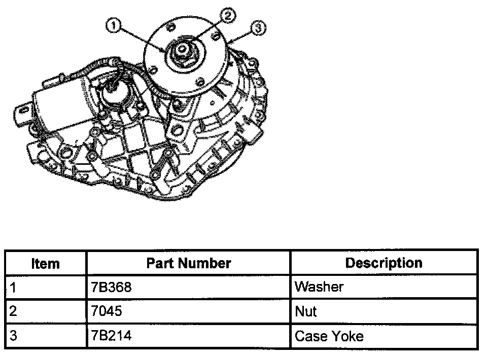
3. Using a 30mm (1.18-inch) thin-wall socket, remove the front output nut, then the output shaft yoke washer, rubber seal and case yoke.
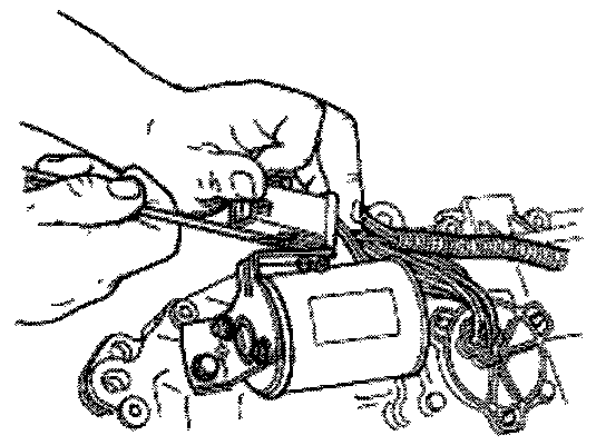
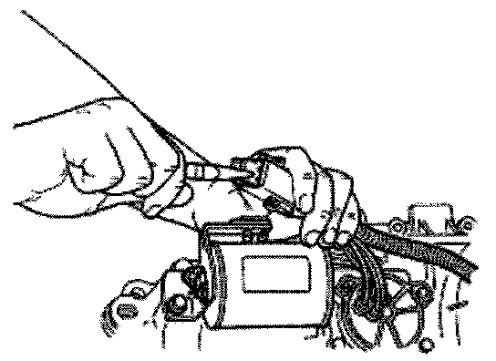
4. Remove wire connector from bracket.
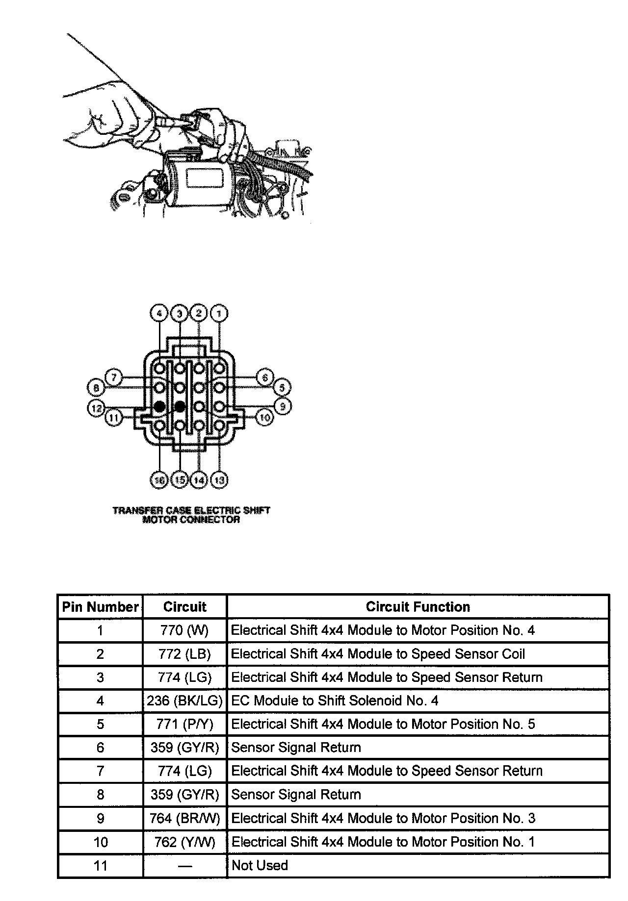
Caution: Do not damage the wire connector locking sleeve.
5. Remove wire connector retainer clip with needle nose pliers.
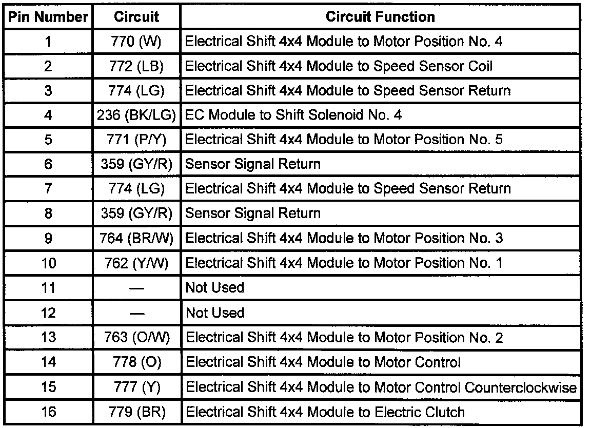
6. Remove six speed sensor wires in connector pin, numbers 2, 3, 4, 6, 7, 8 and coil wire in 16.
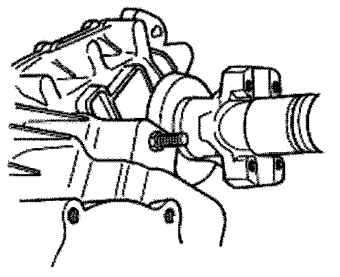
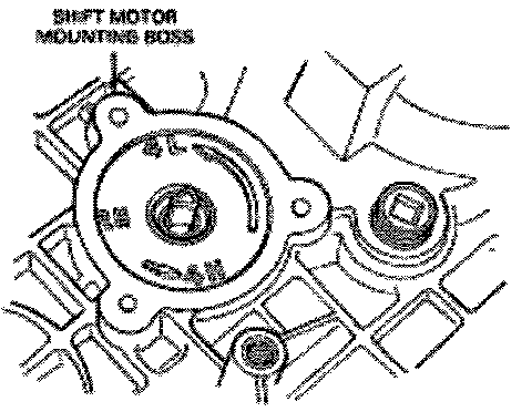
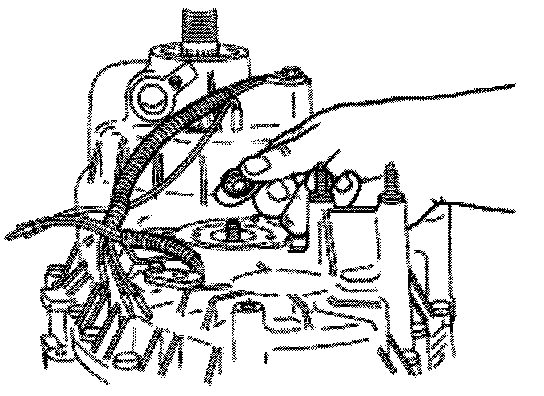
7. Remove the bolts retaining the transfer case shift motor to the rear case (7005) and remove the transfer case shift motor. Note the position of the triangular shaft extending out of the rear case and the triangular slot in the transfer case shift motor.
Caution: When removing the RTV sealant, use care not to damage the mating surfaces of the rear case and motor mounting face.
8. Remove all traces of RTV gasket sealant from the mating surfaces of the rear case and the motor mounting face.
9. Remove speed sensors as required.
Caution: The transfer case shift motor is serviced as a complete assembly. Do not remove the screws that secure the rear case to the motor gear housing.
10. Remove the seventeen bolts retain the front case to the rear case. Make sure that the front case is facing downward so that the rear cover is facing upwards. Pry on the bosses and separate the front case from the rear case. Remove all traces of RTV gasket sealant from the mating surfaces of the front case and rear case.
11. If the speedometer drive gear (17285) is to be replaced, first remove the flange seal by prying and pulling the curved-up lip of the flange seal or use the Impact Slide Hammer T50T-100-A to pop off the flange seal. Do not damage the bearing, bearing cage or case. Remove and discard the flange seal. Remove the speedometer drive gear and upper tone wheel.
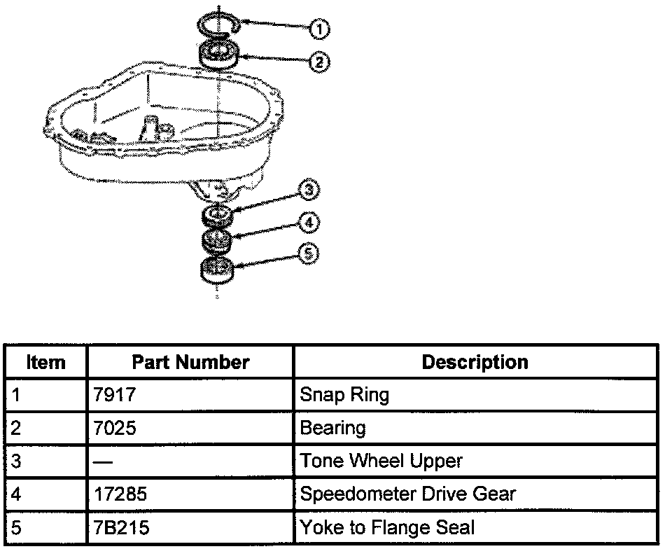
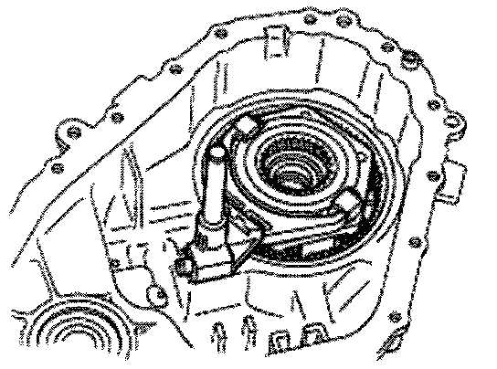
12. If the rear output shaft bearing (7025) requires replacing, remove the internal snap ring that retains the bearing in the bore. From the outside of the case, drive out the bearing using Step Plate D80L-630-A or equivalent and a drift.
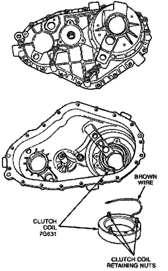
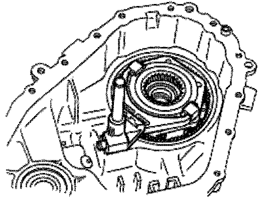
13. Remove the three nuts and washers retaining the clutch coil assembly to the rear case. Pull the assembly, along with the O-ring and brown wire, from the case.
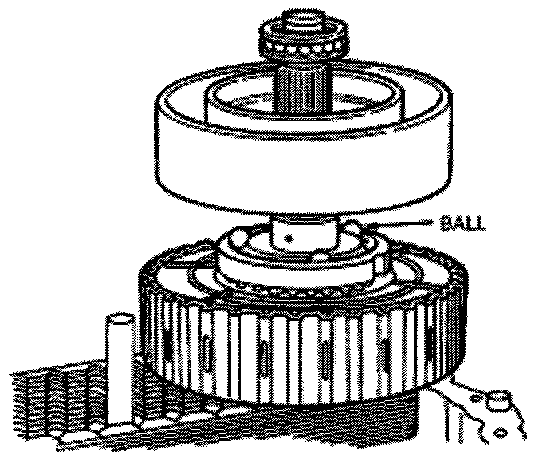
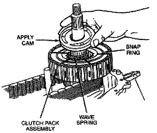
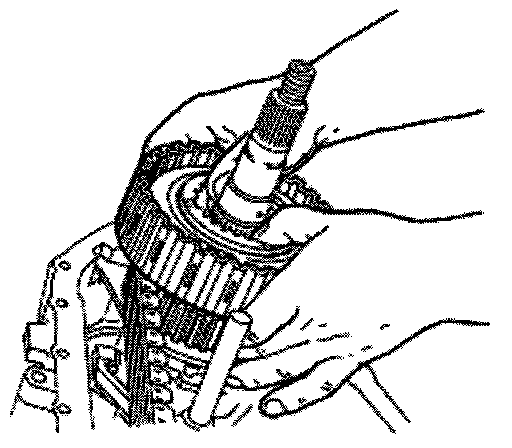
14. Remove the bearing assembly from output shaft. Remove the clutch housing from the output shaft. Remove the balls and apply cam and wave washer from the output shaft. Remove snap ring from output shaft. Remove clutch pack assembly and lower tone wheel from output shaft.
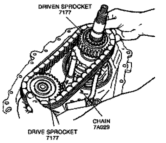
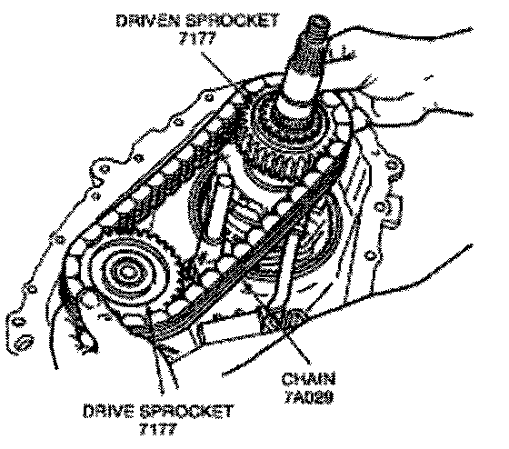
15. Remove the chain, driven sprocket and drove sprocket as an assembly.
16. Remove thrust washer from output shaft.
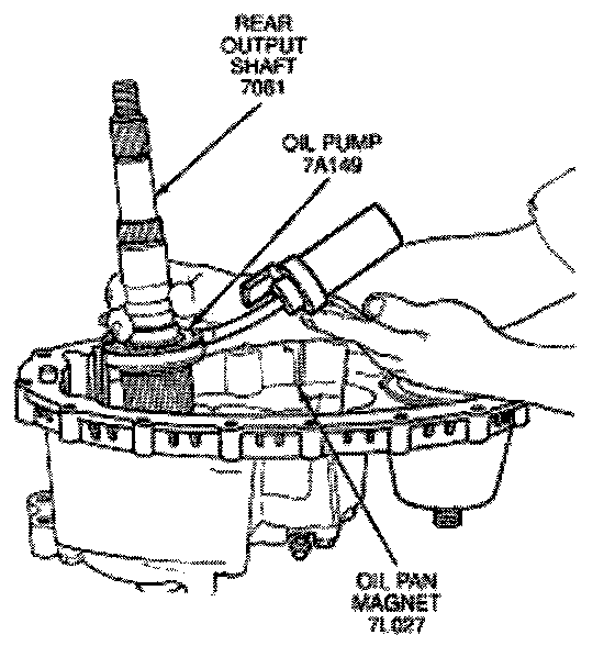
Caution: If there is removal resistance, do not pound or use force to disassemble the pump.
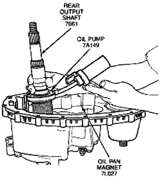
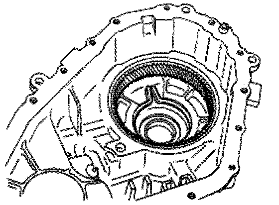
17. Remove the oil pan magnet (7L027) from the slot in the front of the case bottom. Remove the output shaft and oil pump as an assembly.
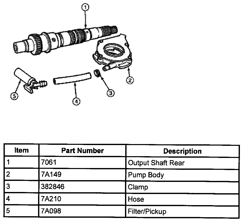
18. If required, to remove the pump from the output shaft, rotate the pump to align.
19. Pull out the shift rail.
20. Remove the helical cam from the front case. If required, remove the helical cam, torsion spring and sleeve from the shaft.
21. Remove the high-low range shaft fork and collar as an assembly.
22. Expand the tangs of the large snap ring in the case using Flat Nose Retaining Ring Pliers TP16A or equivalent. With the input shaft (7017) against a bench, push the case down and slide the main drive gear bearing retainer (7050) off the bearing. Lift the input shaft and front planet (7A398) from the case.
23. If required, remove the oil seal from the case by prying and pulling on the curved-up of the oil seal or use the Impact Slide Hammer T50T-100-A to pop off the oil seal. Do not damage the bearing., bearing cage or case.
24. Remove the internal snap ring from the planetary carrier and separate the front planet from the input shaft.
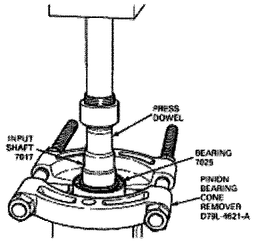
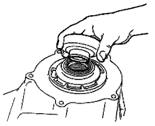
25. Remove the external snap ring from the input shaft. Place the input shaft in a vise and remove the bearing with Bearing Pulling Attachment D79L-4621-A or equivalent. Remove the thrust washer, thrust plate and the sun gear off the input shaft.
Note: Under normal use, the needle bearing and bushing should not require replacement. If replacement is required, the bushing and needle bearing must be replaced as a set.
26. Inspect the bushing and needle bearing in the end of the input shaft for wear or damage.
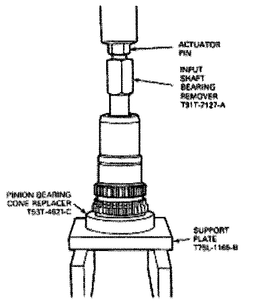
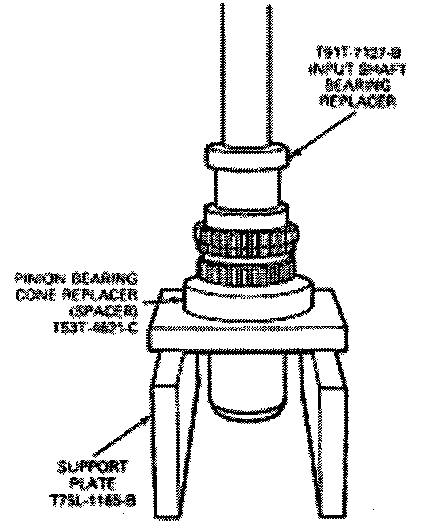
27. If replacement of the needle bearing and bushing is required, press the bearing and bushing out as follows:
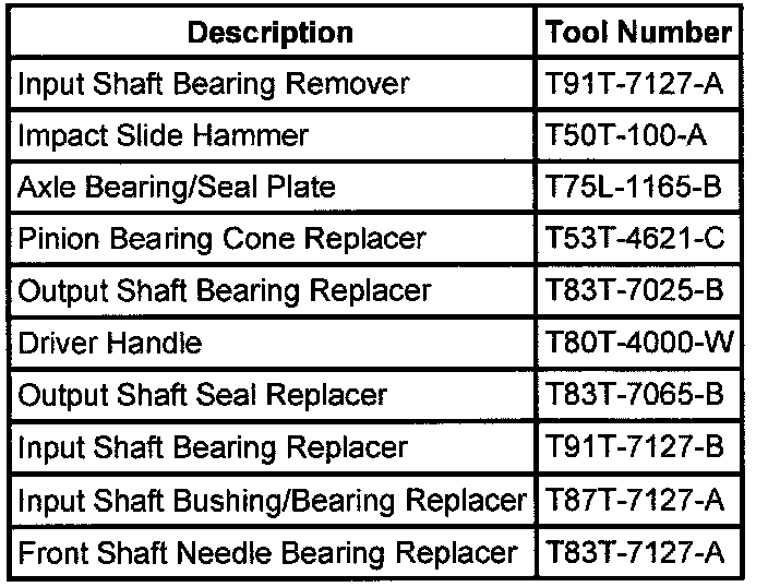
a. Position the input shaft on Axle Bearing/Seal Plate T75L-1165-B, and using Pinion Bearing Cone Replacer T53T-4621-C as a spacer.
b. Insert Input Shaft Bearing Remover T91T-7127-A into the input shaft so it is resting on top of the bearing cage.
c. Tighten the actuator pin until it stops, then press the bearing and bushing out together.
28. If required, remove the front yoke to flange seal (7B215) by prying and pulling on the curved lip of the yoke to flange seal or use the Impact Slide Hammer T50T-100-A to pop off the yoke to flange seal. Do not damage the bearing, bearing cage or case.
29. If required, remove the internal snap ring retaining the front output shaft ball bearing and remove the bearing using Step Plate D80L-630-A or equivalent with a drift.
Assembly
Note: Before assembly, lubricate all parts with MERCON Multi-Purpose Automatic Transmission Fluid XR-2-QDX or DDX or equivalent MERCON fluid.
1. If removed, drive the bearing into the front output case bore using Output Shaft Bearing Replacer T83T-7025-B and Driver Handle T80T-4000-W. Drive the bearing in straight, making sure it is not cocked in the bore. Install the internal snap ring that retains the bearing to the front case.
2. If removed, install the front yoke to flange seal in the front case bore using Output Shaft Seal Replacer T83T-7065-B and driver handle T80T-4000W.
3. If removed, install the yoke to flange seal into the mounting adapter bore. Use Output Shaft Seal Replacer T83T-7065-B and Driver Handle T80T-4000-W or equivalent.
Note: If the input shaft needle bearing and bushing were removed, install a new bearing and bushing as detailed in the following steps:
4. Press a new needle bearing then a new bushing in the input shaft as follows:
a. Position the input shaft on Axle Bearing/Seal Plate T75-1165-B or equivalent, and Pinion Bearing Cone Replacer T53T-462-C as a spacer.
b. Use Input Shaft Bearing Replacer T91T-7127-B, press a new needle bearing into the end of the input shaft until it seals in the input shaft.
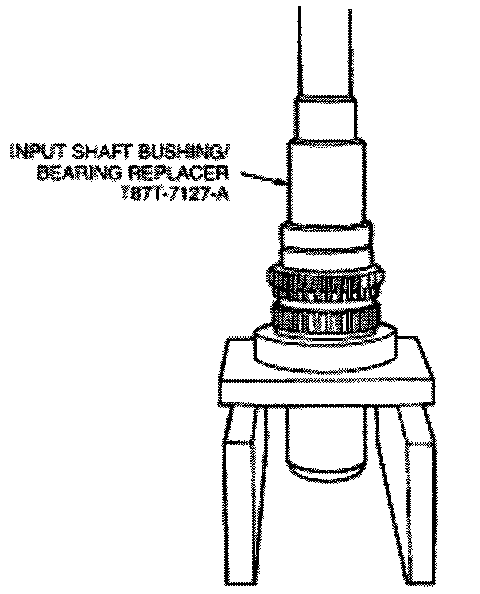
c. Press in a new using using Input Shaft Bushing/Bearing Replacer T87T-7127-A.
Note: The recessed face of the sun gear and the snap ring groove on the bearing outer race should be toward the rear of the transfer case. The stepped face of the thrust washer should face toward the bearing.
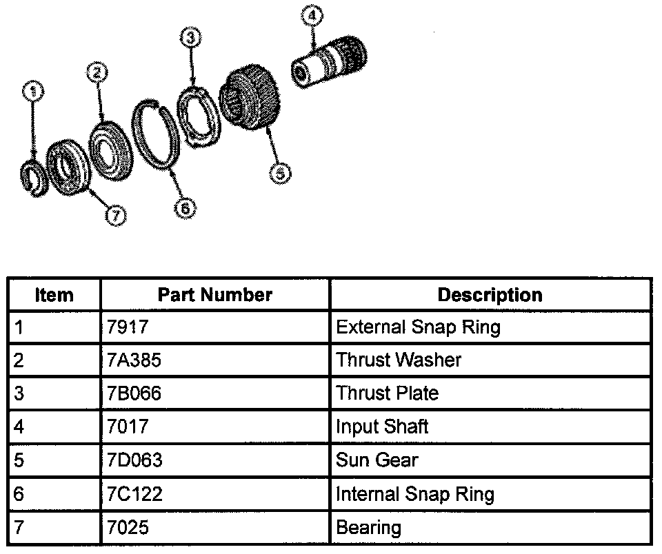
5. Slide the sun gear, thrust plate and thrust washer into position on the input shaft. Press the bearing over the input shaft. Install the external snap ring to the input shaft.
6. Install the front planet to the sun gear and input shaft. Install the internal snap ring to the planetary carrier.
7. Place the tanged snap ring in the case. Expand snap ring pliers and install planetary carrier assembly. Check installation by holding the case and carefully tapping the face of the input shaft against a wooden block to make sure the snap ring is installed.
8. Remove all traces of RTV gasket sealant from the front case and mounting adapter mating surfaces. Install a bead of RTV gasket-sealant on the surface of the front case. Use Black Non-Acid Cure Silicone Rubber E7TZ-19562-A or equivalent meeting Ford specification ESL-M4G273-A.
Note: Make sure that the nylon wear pads are installed on the shift fork and snapped securely into place.
9. Install the high-low shift fork and high-low collar as assembly into the front planet.
Note: Do not disassemble oil pump. It is serviced only as assembly. Check the pump to make sure the pump rotates freely.
Note: Do not remove plastic insert from the bore of the new pump. Discard it after it slides out during pump installation to the rear output shaft.
Note: While turning the output shaft, prime the pump through the oil filter pickup tube or housing inlet hole with clean Motorcraft MERCON Multi-Purpose Automatic Transmission Fluid Xt-2-QDX or DDX or equivalent MERCON fluid.
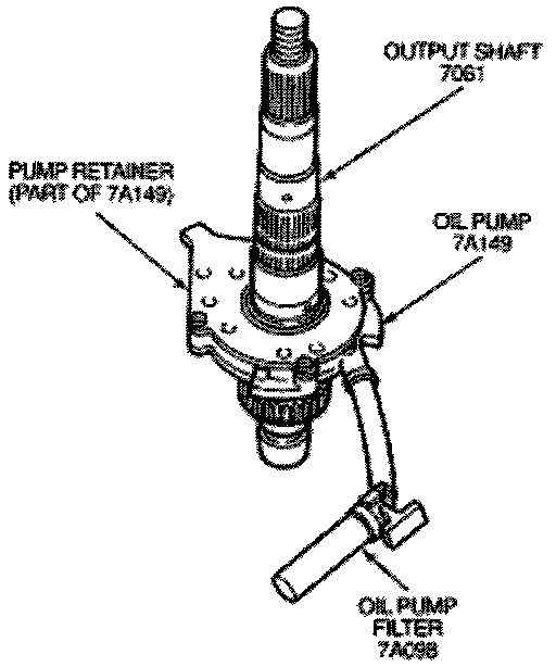
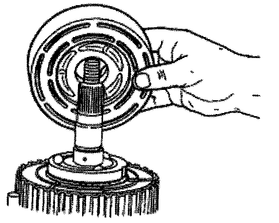
10. If new pump is used align the flat of the output shaft and the flat of the pump. Slide the pump onto the output shaft.
11. Inspect the outside surfaces and bore of the oil pump. If there is no discoloration in the pump housing, gear or cover, and the pump bore and the lube holes of the output shaft show evidence of oil, the the pimp is working.
12. Install the output shaft and oil pump in the input shaft. Make sure that the internal splines of the output shaft engage the internal splines of the high-low shift collar. Make sure that the oil pump retainer arm and oil filter leg are in the groove and slot of the front case.
13. Install the oil pan magnet in the slot in the front case just above the oil filter leg.
14. Install the front output shaft in the front case.
Note: The driven sprocket (on the front output shaft) must be installed with the marking REAR facing toward the rear case, if so marked.
Note: Drive sprocket has a bushing pressed into it.
15. Install the thrust washer (7119) on the rear output shaft. Install the chain, Drive sprocket and driven sprocket. as an assembly over the output shaft.
16. Install tone wheel onto the front output shaft. Make sure the spine on the tone wheel engages the spline on the front output shaft.
17. Install clutch pack assembly onto the rear output shaft. Make sure the spline of the clutch pack engages to the spline of the sprocket.
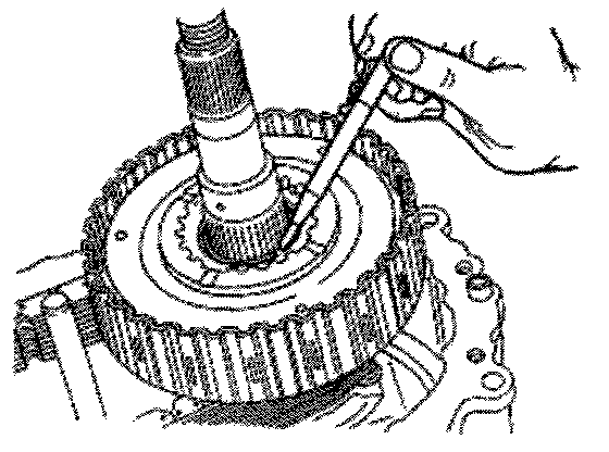
18. Install snap ring onto the rear output shaft. Start the snap ring over the spline and use the wave spring to seat the snap ring in the snap ring groove. If the snap ring will not install, the thrust washer inside the clutch pack may not seated properly.
Note: Three slots on the thrust washer must be aligned with the three tabs on the clutch pack housing.
19. Install wave spring, insulator washer and armature. (Three off set slots must align with housing to be installed.)
20. Install apply cam onto the rear output shaft, install three balls into the apply cam, install cam and coil housing assembly onto output shaft. Install thrust bearing assembly onto output shaft.
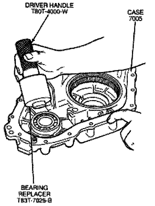
21. If removed, drive the front output shaft ball bearing into the rear cover bore with Front Shaft Needle Bearing Replacer T83T-7025-B and Driver Handle T80T-4000-W.
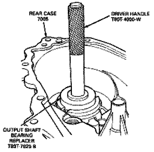
22. If removed, Install the rear output bearing in the rear case bore. Drive the bearing into the rear case bore with Output Shaft Bearing Replacer T83T-7025-B and Driver Handle T80-T-4000-W. Make sure that the bearing is not cocked in the bore. Install the internal snap ring that retains the bearing to the rear case.
Caution: Do not kink or trap the wire while seating the clutch coil to the case.
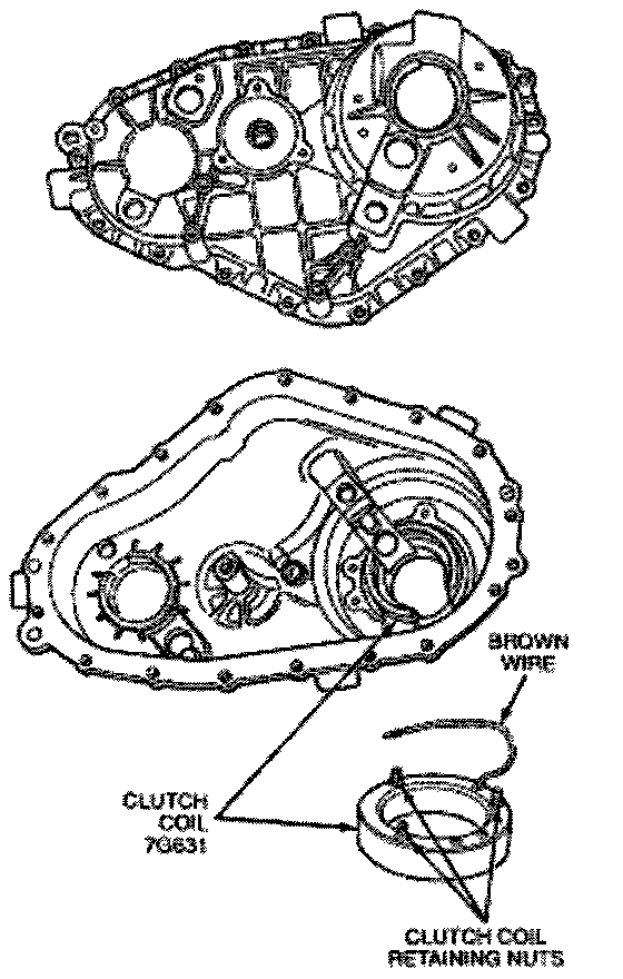
23. Install the clutch coil from inside the rear case until the wire and studs extend through the cover. Install the washers and nuts and tighten to 8 - 11 Nm ( 72 - 96 lb in ).
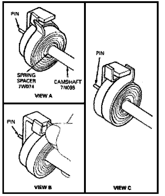
24. Slide the spring spacer on the camshaft and position it beneath the drive tang. Place the torsion spring on the camshaft. Position the first spring tang to the left of the camshaft drive tang (view A). Wind the second spring tang clockwise past the drive tang (view B). Push the torsion spring and sleeve in as far as it will go (view C). This will seat the second spring tang on the right side of the drive tang. Install the helical cam and slide the drive tang between the torsion spring tangs as far as it will go.
Caution: Do not bend the helical cam during installation to the front case because of possible damage to the pin at the tang end of the motor shaft.
25. Install the pinion on the tang end of the helical cam into the hole in the front case. Position the torsion spring tangs so that they are pointing towards the top side of the transfer case and just touching the high-low shift fork,
26. Install the shift rail through the high-low shift fork and make sure that the reverse gear shift rail (7240) sensor wire shield.
Note: The upper speed sensor has a linger wire.
27. Install upper and lower speed sensor into the cover. Feed the coil wire through the upper speed sensor wire shield.
28. If damper support studs are not installed, install studs using a Torx driver. Tighten to 27 - 35 Nm ( 20 - 26 lb ft ).
29. Install the upper tone wheel, speedometer gear and rear output seal. Use Output Shaft Seal Replacer T83T-7065-B and Driver T80T-4000-W or equivalent to install seal.
30. Coat the mating surface of the front case with a bead of Black Non-Acid Cure Silicone Rubber E7TZ-19562-A or equivalent meeting Ford specification ESL-M4G273-A
31. The following procedure must be followed prior to installing the rear case onto the front case half:
a. Align the output shaft with the rear case output shaft bore.
b. Align the helical cam with the rear case motor bore.
c. Align the rear case so that the spring boss engages the lockup return spring and shift rail.
Note: If difficulty is encountered with seating the rear case, tap the rear case output shaft with a sharp low
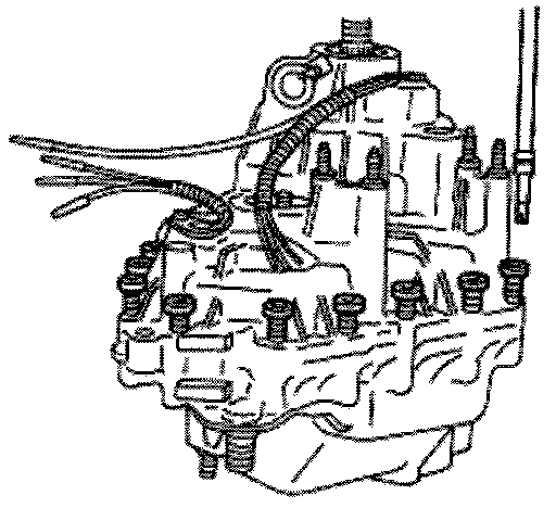
32. Install the bolts retaining the case halves and tighten to 27 - 35 Nm ( 23 - 30 lb-ft ).
33. Install shift shaft oil seal if it is not installed, using Shift Shaft Seal Tool T87C-6510-B or equivalent.
Note: During motor installation, if the shaft will not stay in the 4H position, rotate the transfer case shift motor counterclockwise until the transfer case shift motor is aligned with the mounting holes.
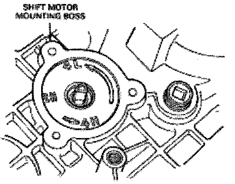
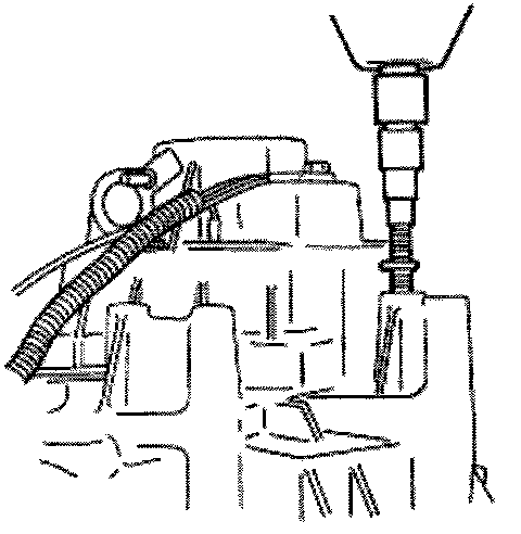
34. Using pliers equipped with soft jaws, rotate the triangular shaft so it is aligned with the triangular slot in the transfer case shift motor. If triangular shaft will not rotate, rotate the rear output shaft.
35. Slightly loosen the two nuts that attach the slotted support bracket to the end of the motor house.
36. Apply Black Non-Acid Cure Silicone Rubber E7RZ-19562-A or equivalent meeting Ford specification ESL-M4G273-A to motor housing base and install on transfer case.
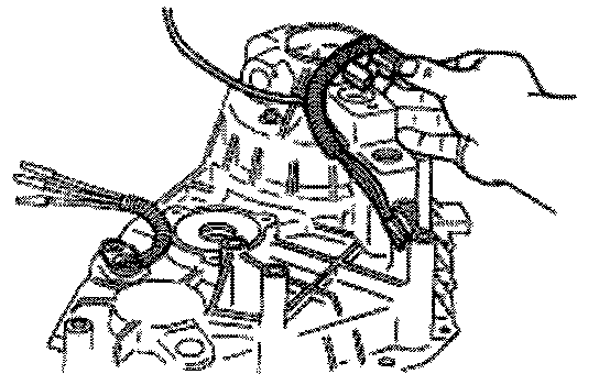
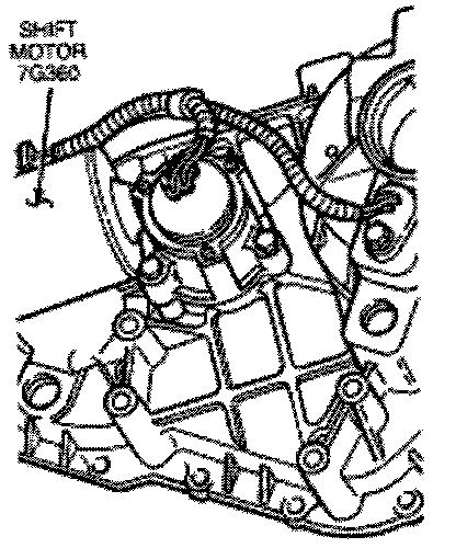
Note: The wire harness must be routed as show to provide clearance and to prevent the wire harness from grounding the damper.
37. Install the transfer case shift motor and three bolts along with speed sensor wire harness bracket. Tighten to 8 - 11 Nm ( 71 - 97 lb-in ).
38. Holding the slotted support bracket tight against the motor housing end, secure the bracket to the transfer case, tightening the bolts with lockwasher to 8 - 11 Nm ( 71 - 97 lb-in ).
39. Retighten the two nuts that attach the slotted support bracket to the end of the motor to 3 - 4 Nm ( 27 - 35 lb-in ).
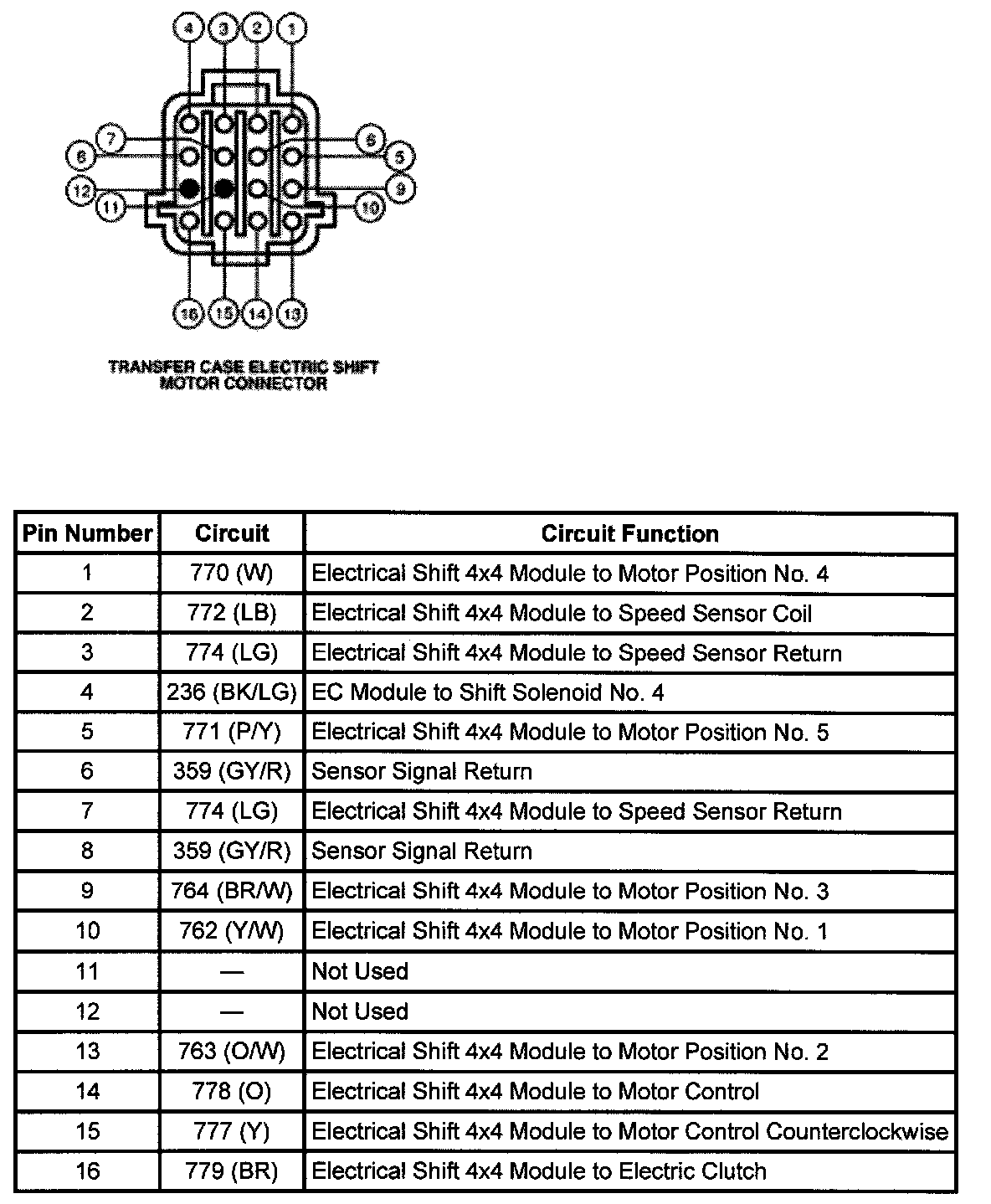
40. Install the brown clutch coil wire terminal and sensor wires using schematic terminal.
41. Install connector retainer.
42. Install the rear case flange on the output shaft. Install the rubber seal, output shaft yoke washer and nut. Tighten the nut to 338 - 371 Nm ( 250 - 275 lb ft ).
43. Install the drain plug and tighten to 19 - 30 Nm ( 14 - 22 lb-ft ).
44. Install the front case flange, rubber seal, output shaft yoke washer and the nut to front output shaft. Tighten the nut to 203 - 244 Nm ( 150 - 180 lb ft ).
45. Fill the transfer case with 1.2 liters (2.5 U.S. pints) of Motorcraft MERCON Multi-Purpose Automatic Transmission Fluid XT-2-QDX or DDX or equivalent MERCON fluid.
46. Install the fill plug and tighten to 19 - 30 Nm ( 14 - 22 lb-ft ).
Note: Make sure proper drain and fill plugs are installed if case is replaced,
47. Install the transfer case.