Brake Pad: Service and Repair
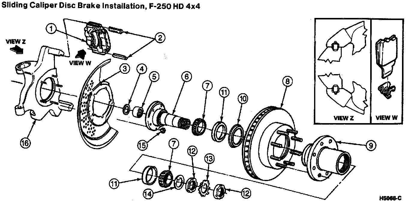
ITEM PART DESCRIPTION
NUMBER
1 2B120 Front Disc Brake Caliper
2 2C150 Pin Assembly
3 2K004 Front Disc Brake Rotor Shield
4 1175 Seal
5 3423 Bearing
6 3105 Front Wheel Spindle
7 4221 Differential Bearing
8 1125 Rotor
9 1102 Hub
10 1125 Wheel Seal
11 4222 Differential Bearing Cup
12 1197 Locknut
13 1B198 Lockwasher
14 1C245 Thrust Washer
15 35704 Dana Nut
16 3130, Steering Knuckle
3131
NOTES
- Replace brake shoe and lining when the lining is worn to a minimum thickness of 0.794mm (1/32 inch) above the brake backing plate (2211).
- Always replace all brake shoes and linings on an axle. Never service one wheel (1007) only.
REMOVAL
1. To avoid fluid overflow when the caliper pistons are pressed into the caliper cylinder bores, siphon or dip part of the brake fluid out of the brake master cylinder reservoir. Discard the removed fluid.
2. Raise the vehicle and install safety stands. Remove the front wheel and tire assembly.
NOTE: Do not use a screwdriver or similar tool to pry wheel cylinder piston away from the front disc brake rotor.
Brake Caliper Compressing Procedure:
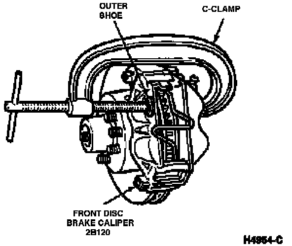
3. Place an appropriate size C-clamp on the front disc brake caliper with end of clamp against caliper and end of screw against outer shoe. Tighten the clamp to bottom the caliper pistons in the cylinder bores. Remove the clamp.
4. Clean excess dirt from area around pin tabs.
5. Tap upper caliper pin toward inboard side until pin tabs touch the front wheel spindle.
Caliper Pin Removal:
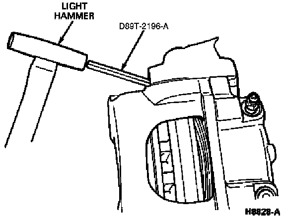
6. Using Caliper Pin Remover D89T-2196-A or equivalent and a light hammer, drive the pin from the front disc brake caliper as follows:
a. Position the notched end of the tool against the caliper pin (retention tab half), at a 45° angle from the pin retention tabs.
b. Tap the tool with the hammer to compress the retention tabs.
Caliper Pin Removal:
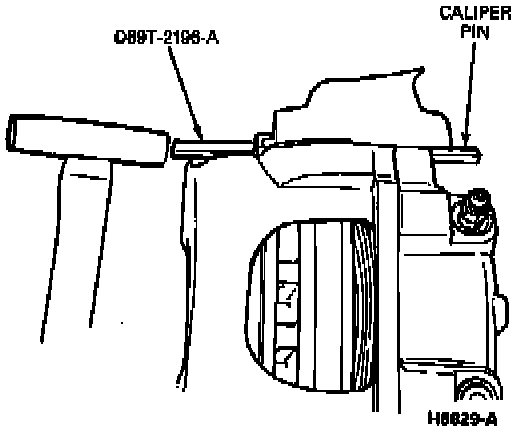
c. As the retention tabs are compressed, move the tool to gain a straight approach to the pin, and continue tapping to drive the pin through the caliper/spindle groove.
7. Repeat removal procedure for lower pin.
CAUTION: Do not let the front disc brake caliper hang by the front brake hose (2078). The front brake hose could become stretched or twisted which can cause the front brake hose to leak and rupture, resulting in failure.
8. Remove the front disc brake caliper from the front disc brake rotor. If the front disc brake caliper is to be removed for service, remove the front brake hose from the front disc brake caliper. Plug the end of the front brake hose to prevent fluid loss and entry of air into the system. If the front disc brake caliper is not to be removed, wire it up to the frame (5005) of the vehicle to avoid damage to the front brake hose.
9. Remove the outer and inner lining and remove the disc brake pad anti-rattle clip (2B164).
INSTALLATION
NOTE: There is a raised section at one end of each shoe so installation can be made in one direction only.
1. Install new inner and outer lining. Install disc brake pad anti-rattle clip.
NOTE: Always replace all brake shoes and linings on an axle. Never service one wheel only.
2. Lubricate the knuckle upper and lower inner pad grooves and caliper grooves with Disc Brake Caliper Slide Grease D7AZ-19590-A (ESA-M1C172-A) or equivalent. Install the front disc brake caliper on a front wheel spindle making sure the mounting surfaces are free of dirt.
CAUTION: During the installation procedure do not allow the tabs of the caliper pin to be tapped too far into the spindle groove. If this happens it will be necessary to tap the other end of the caliper pin until the tabs snap into place. The tabs on each end of the caliper pin must be free to catch on the spindle flanks.
3. Position pin with the pin retention tabs oriented adjacent to the spindle groove.
Caliper Pin Installation:
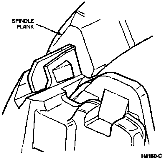
4. Tap the pin on the outboard end with a hammer. Continue tapping the pin inward until the retention tabs on the sides of the pin contact the spindle face. Repeat procedure for the lower pin.
5. If removed, install the front brake hose to the front disc brake caliper and perform brake bleeding procedure.
6. Install the wheel and tire. Tighten the lug nuts to 190 Nm (140 ft lb).
7. Lower the vehicle, check the brake fluid level and fill as necessary. Check front disc brake calipers for proper operation.