Model 44-IFS
NOTE: When changing ratios on the front drive axle, it may be necessary to change the differential case along with the ring gear and drive pinion. Ratios 2.72 to 1 up to 3.73 to 1 incorporate a thick differential case flange and a thin ring gear. Ratios 3.92 to 1 up to 4.09 to 1 incorporate a thin differential case flange and a thick ring gear.
1. Remove axle assembly from vehicle, please refer to Transmission and Drivetrain/Drive Axles, Bearings and Joints/Axle Shaft Assembly/Axle Shaft/Service and Repair/ Service and Repair
2. Loosen bolts retaining carrier to axle arm and drain fluid.
3. Remove right hand slip yoke and stub shaft.
4. Remove bolts attaching support arm to carrier, then the carrier assembly.
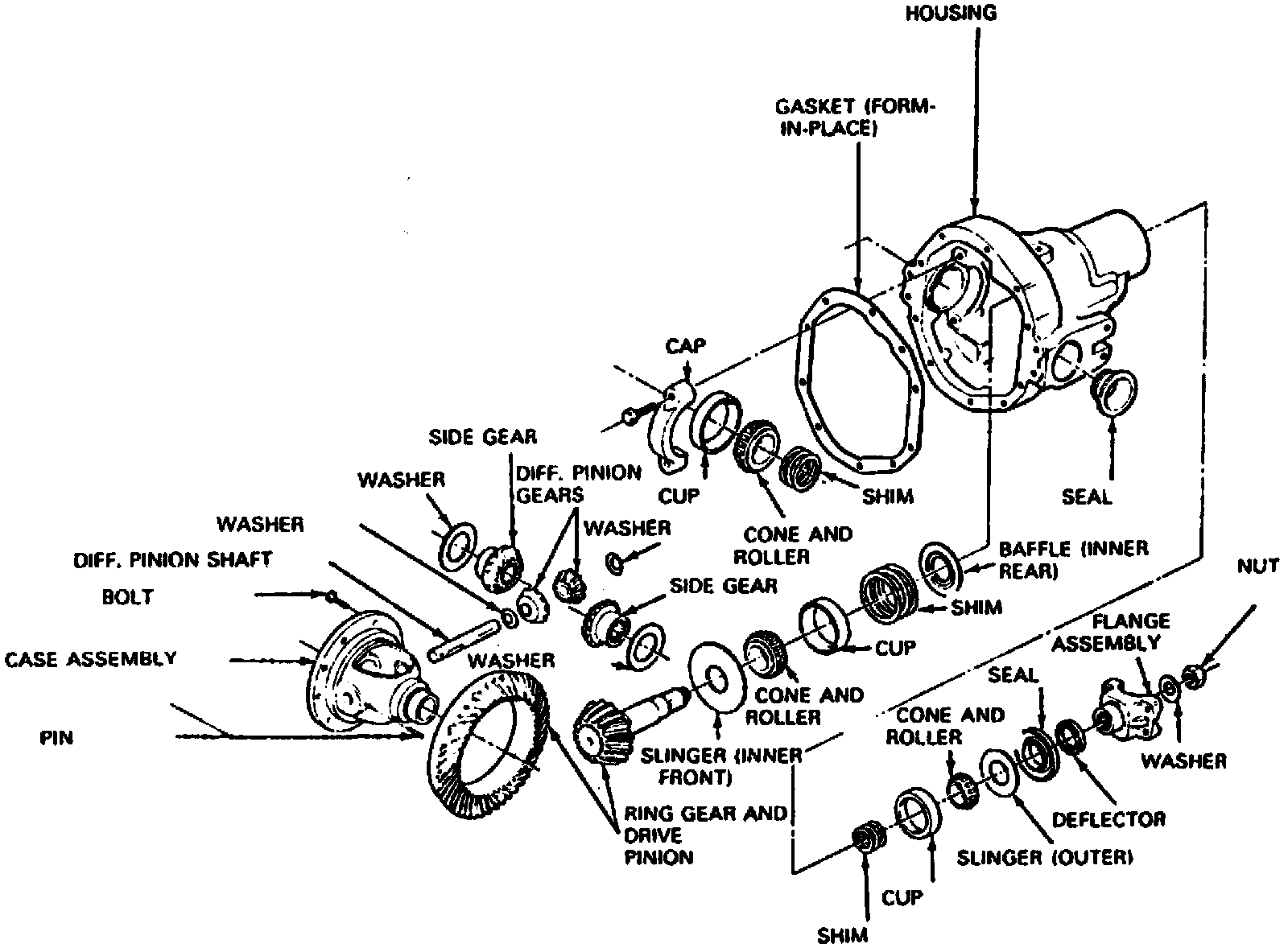
Fig. 4 Exploded View Of Model 44-1FS-HD & 50-1FS Axles:
5. Place carrier into tool No. T57L-500-B, or equivalent, using adapter plate tool No. T90T-4000-A and spacer tool No. T80T-4000-B2, or equivalents, then remove and clean all gasket surfaces. Remove bearing caps. Note matched numbers or letters stamped on the cap and carrier assembly. These numbers or letters must be matched during assembly. The numbers may either be stamped vertically, horizontally or in some instances both vertically and horizontally.
6. Mount spreader tool No. 4000-E and spreader adapter tool No. T80T-4000-B, or equivalents, onto carrier assembly.
7. Position a dial indicator onto carrier, then spread housing.
NOTE: Do not spread housing more than 0.010 inch.
8. Remove differential case from carrier. It may be necessary to pry case from carrier with suitable pry bars. Use care to avoid damaging machined surfaces.
9. Remove and tag bearing cups to indicate which side of carrier they were removed from, then remove spreader tool from case.
10. Remove and tag selective shims located on each side of differential bearing bore to indicate side of carrier from which they were removed. Inspect shims for damage, bending or deep grooves. If damaged, replace during reassembly procedure.
11. Turn nose of carrier upward, hold end yoke with tool No. T57T-4851-B, or equivalent, then remove pinion nut and washer from pinion assembly.
12. Using yoke remover tool No. T77F-4220-B1, or equivalent, remove end yoke. If yoke shows any sign of wear in seal contact area, replace yoke.
13. Remove drive pinion by tapping on drive pinion shaft using a rawhide or plastic hammer. Catch pinion to prevent damage to pinion teeth. Use care not to damage pinion bearing preload shims located on the splined end of pinion. If damaged, replace with shims of equal thickness. Do not lose shims.
WARNING: Gear teeth may have sharp edges, use care when handling gear to prevent personal injury.
14. Using bearing cup puller tool No. T77F-1102-A, or equivalent, and a suitable slide hammer, remove drive pinion oil seal from carrier.
15. Remove outer pinion bearing and oil slinger from carrier input bore.
16. Remove pinion bearing preload shims. Ensure all shims are removed from the carrier. Replace any damaged shims. Shims are available in thicknesses of 0.003, 0.005, 0.010 and 0.030 inch.
17. Remove inner pinion bearing cup and baffle using a suitable pinion bearing cup remover and driver handle. Pass bearing cup remover and drive handle through outer bearing cup and place against inner bearing cup, then drive inner bearing cup out of bore. Use care not to damage oil baffle when removing inner bearing cup.
18. Remove oil baffle from inner bearing cup bore. Oil baffle is located between the inner bearing cup and carrier bore. Shims are located between the inner bearing cup and baffle. Do not damage the shims when removing the bearing cup.
NOTE: If any shims are damaged, measure the thickness and replace with shims of equal thickness.
19. Turn nose of carrier downward and remove outer pinion bearing cup using a suitable pinion bearing cup remover and driver handle. Pass bearing cup remover and drive handle through inner bearing cup bore and place against outer bearing cup, then drive outer bearing cup out of bore.
20. Remove differential case bearings and shims from case. Position step plate tool No. D80L-630-4, or equivalent, under bearing, then install universal bearing remover tool No. D81L-4220-A, or equivalent, and remove bearing. Turn case over and remove other bearing in the same manner.
21. Wire shims, bearing cup and cone together and identify from which side of differential case they were removed.
NOTE: If any shims are damaged, replace with new shims. It is recommended that bearings be replaced.
22. Place a few shop towels over a vise to prevent ring gear teeth from being nicked after it is free from case assembly. Remove ring gear bolts. Tap ring gear with a rawhide or plastic hammer to free it from case. Remove case and ring gear from vise.
NOTE: Whenever removing ring gear bolts, discard and replace with new bolts upon assembly.
23. Remove bearing and oil slinger from drive pinion using tool No. D81L-4220-A, or equivalent. For controlling drive pinion depth, an oil slinger with a selective thickness is used.
NOTE: If oil slinger is damaged, measure thickness and replace with a slinger of equal thickness.
24. Inspect all parts for damage and replace as required.