Load Compensator: Service and Repair
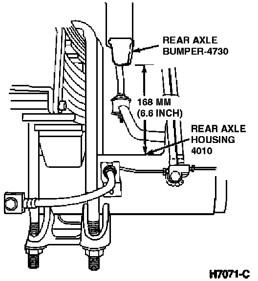
REMOVAL1. With the rear wheels on the ground, lift the frame to obtain a 168mm (6.6 in.) clearance between the bottom edge of the rear axle bumper and the top of the rear axle housing (both sides). The suspension is now in the correct position for installing the pre-indexed brake load sensor proportioning valve.
2. Remove the nut holding the linkage arm to the brake load sensor proportioning valve and disconnect the linkage arm.
3. Remove the flow bolt holding the rear brake hose to the brake load sensor proportioning valve.
4. Disconnect the brake tube from the brake load sensor proportioning valve.
5. Remove the two bolts securing the brake load sensor proportioning valve to mounting bracket, remove the brake load sensor proportioning valve.
INSTALLATION
1. Place the brake load sensor proportioning valve on its mounting bracket. Install the two (2) mounting bolts and tighten to 29.7-40.3 Nm (22-29 lb ft).
2. Install the rear brake hose using new copper gaskets. Tighten the flow bolt to 23-34 Nm (17-25 lb ft).
3. Install the brake tube to the lower port on the brake load sensor proportioning valve and tighten securely.
4. Position the linkage arm on the brake load sensor proportioning valve and tighten the retaining nut to 14.8-20.2 Nm (11-14 lb ft).
5. Bleed the brakes. Check for proper brake operation. Refer to Brake Bleeding.