Glow Plug System Operation
PURPOSE
To determine if the glow plug system operation is sufficient to permit starting.
RECOMMENDED PROCEDURE
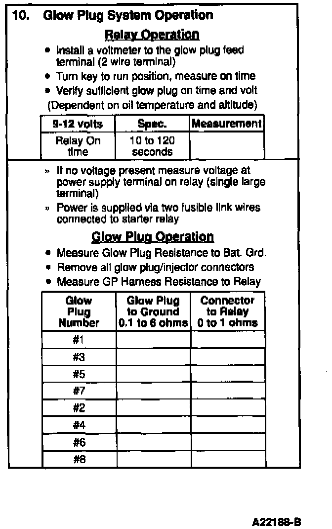
Relay Operation
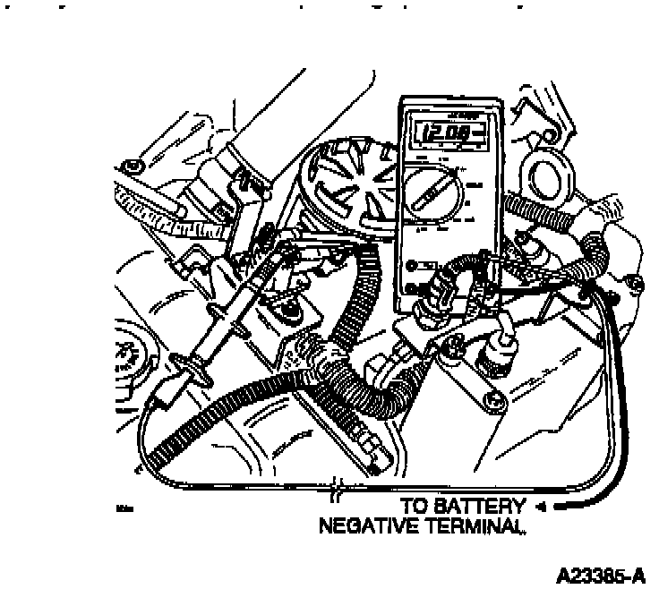
Install a Digital Volt-Ohmmeter (DVOM) on the glow plug feed side of the glow plug relay (large stud with two wires connected). Turn the ignition key to the ON position but do not attempt to start. Note the time in seconds from when the key is turned on and the glow plug relay energizes until the glow plug relay de-energizes. The glow plug relay makes a loud click noise which is easily heard when it energizes and de-energizes. The dome light will dim and the dash voltmeter will dip when the glow plugs are drawing current from the battery. Compare the times measured to the table (time will be affected by engine temperature, battery condition and vehicle altitude). The voltage at the glow plug feed terminal may vary from 9 to 12 volts depending upon battery condition.
If battery voltage not present check for B+ at power supply terminal (terminal with single large wire). Power for glow plug power supply is supplied from starter relay through two fusible links at solenoid.
Glow Plug Operation
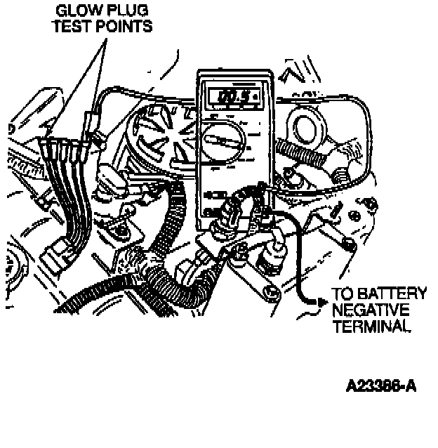
Disconnect all of the glow plug/injector harness connectors from the valve cover gaskets. With the pigtail installed, measure glow plug resistance to ground (preferably B-). A resistance measurement of 0.1 to 6 ohms indicates a good glow plug.
Glow Plug Harness Testing:

Glow Plug Harness Continuity
Measure for continuity from the connector harness to the glow plug feed terminal on the glow plug relay. Resistance should be less than 5 ohms.
NOTE: Incorrect measurements will result if all glow plug/injector connectors to valve cover are not disconnected.
POSSIBLE CAUSES
Insufficient glow plug ON time will not allow enough heat to accumulate in the combustion chamber to easily facilitate starting. If the glow plug system ON time does not meet any of the specifications in the accompanying chart the problem is most likely a faulty wire harness connection, ground connections or glow plug relay.
If the glow plug resistance to ground is high, the most likely causes are an open Under Valve Cover (UVC) harness or open glow plug.
TOOLS REQUIRED
- Rotunda DVOM 105-00050
- Pigtail connector
- Stop watch