Part 2 of 2
49. Make sure chain cover alignment pins are on case.CAUTION: Be extremely careful to prevent damage to the input shaft cast iron sealing ring.
Chain Cover Bolt Installation:

50. Carefully align chain cover input shaft bore with input shaft. Apply gentle downward pressure on chain cover to overcome accumulator spring pressure and start two chain cover bolts. If removed, install Turbine Shaft Speed (TSS) sensor.
NOTE: After installing chain cover, input shaft should have some end play and should rotate freely. If it will not rotate freely. remove chain cover and inspect cast iron seal for damage.
Chain Cover Bolt Torque Sequence:

51. Start remaining chain cover bolts and tighten 10mm bolts to 27-33 Nm (20-26 ft-lb). Tighten 8mm bolt to 9-12 Nm (7-9 ft-lb). Tighten 13mm bolt to 34-48 Nm (26-35 ft-lb). Tighten bolts in sequence shown.
52. Install TSS sensor.
53. Install output shaft seal and circlip.
54. Install output shaft seal using Output Shaft Seal Replacer T86P-1177-B.
55. Install new tubes in position and tap lightly until fully seated.
NOTE: When installing the rear lube tube, install the long end into the rear planet support and seal first.
Tube Support Brackets:

56. Install tube support brackets.
Reverse Drum Anchor Bolt:

57. Tighten reverse drum 6mm Allen head anchor bolt to 10-12 Nm (7-9 ft-lb) and 19mm locknut to 34-47 Nm (26-35 ft-lb).
Installing Filter And Filter Seal:

58. Install filter seal onto filter and press filter into case.
Transmission Pan Magnet:

59. Install magnet in transaxle pan.
60. Install new pan gasket on case and install transaxle pan. Tighten bolts to 13-15 Nm (8-11 ft-lb).
Air Pressure Checks:

61. Perform air pressure checks using Transmission Test Plate T91P-7006-A. After pressure checks have been performed, remove tool.
NOTE: When applying regulated 276 kPa (40 psi) air pressure to the appropriate passage, a dull thud should be heard when the clutch or band applies. There should be no hissing sound when clutch or band is applied.
Oil Pump Shaft Seals:

62. Install four new Teflon(R) pump shaft rear seals and pump shaft front seals on pump shaft and install pump shaft.
CAUTION: Seals must be lapped correctly or internal leakage will occur.
Manual Valve Link And Detent Lever:

63. Connect manual valve link to manual detent lever.
64. Start pump and main control valve body over oil pump shaft. Connect manual valve link to manual shift valve. Push main control valve body down until seated.
Main Control Valve Body Bolt Locations:

65. Install 22 main control valve body bolts and tighten in sequence to 9-12 Nm (7-9 ft-lb).
Electrical Connectors:

66. Install electrical connectors on proper solenoids and sensor until a slight click is felt.
67. Install pump and main control valve body cover gasket onto cover.
Main Control Valve Body Cover:

68. Install cover and tighten to 21-25 Nm (15-18 ft-lb).
69. Rotate transaxle to horizontal position.
70. Place shift control selector lever in the NEUTRAL position.
Transmission Range Sensor:

71. Install Transmission Range (TR) sensor and loosely install two retaining bolts.
72. Align TR sensor slots using Transmission Range Sensor Alignment Tool (MLPS Alignment Tool) T92P-70010-AH.
73. Tighten retaining bolts to 9-12 Nm (7-9 ft-lb). Remove tool.
Chain Cover Bolts:

74. Install remaining chain cover bolts in bellhousing and tighten bolts to 25-28 Nm (18-21 ft-lb) for 10mm and 9-12 Nm (7-9 ft-lb) for 8mm bolts.
Operating And Test Springs:

75. Install test spring, from Overdrive Servo Rod Tool T86P-70023-B in case.
CAUTION: The test spring from the Overdrive Servo Tool is plain in color and has a shorter free height than the operational spring. Extreme care must be used not to assemble the transaxle using the test spring.
76. Install overdrive servo piston and overdrive servo rod into case.
Servo Rod Tool:
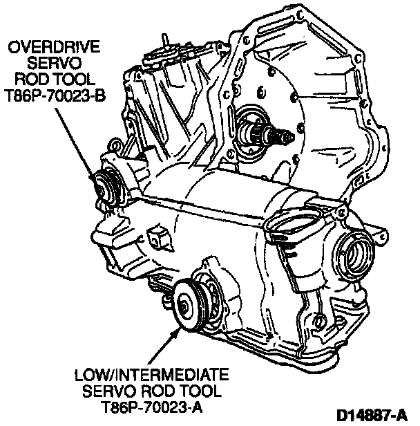
77. Install Overdrive Servo Rod Tool T86P-70023-B and secure using servo cover bolts. Tighten bolts to 9-12 Nm (7-9 ft-lb).
78. Tighten center screw on tool to 1.13 Nm (10 in-lb).
Dial Indicator:

79. Mount Dial Indicator with Bracketry TOOL-4201-C or equivalent and position stylus through hole in Overdrive Servo Rod Tool. Make certain indicator stylus has contacted overdrive servo piston on a flat surface. Do not contact step on piston. Zero dial indicator.
Overdrive Piston Rod Selection Chart:
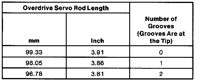
80. Back off center screw until piston movement stops and read dial indicator. The reading should be 1.8-3.8 mm (0.070-0.149 inch). If measurement does not meet specifications, refer to overdrive piston rod selection chart to determine which overdrive servo rod to install.
81. If incorrect, install new overdrive servo rod and repeat Steps 85 through 89 to verify amount of piston travel. If within specifications, remove tool and test spring.
Servo Pistons And Test Springs:

82. Install low and intermediate servo spring retainer on test spring, from Low/Intermediate Servo Rod Tool T86P-70023-A. Install test spring into case.
Operating And Test Springs:
CAUTION: The test spring from the Low/Intermediate Servo Tool is plain in color and has a thinner wire diameter than the operational spring. Extreme care must be used not to assemble the transaxle using the test spring.
83. If not done previously, remove servo piston small seal from servo band piston. Install servo band piston and rod into case.
84. Install Low/Intermediate Servo Rod Tool T86P-70023-A and secure using servo cover bolts. Tighten bolts to 9-12 Nm (7-9 ft-lb).
85. Tighten center screw on tool to 3.4 Nm (30 in-lb).
Dial Indicator:
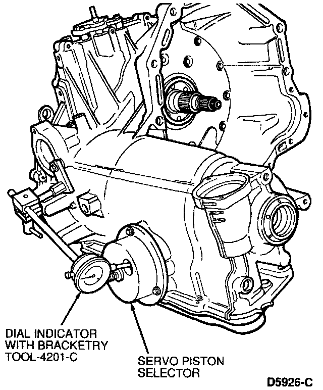
86. Mount Dial Indicator with Bracketry TOOL-4201-C or equivalent and position stylus through hole in Low/Intermediate Servo Rod Tool. Make certain indicator stylus has contacted servo band piston on a flat surface. Do not contact step on servo band piston. Zero dial indicator.
NOTE: If a new low and intermediate band is installed, reading should be 5-6 mm (0.197-0.236 inch).
Low/intermediate Piston Rod Selection Chart:

87. Back off center screw until piston movement stops and read dial indicator. The reading should be 5.5-6.5 mm (0.216-0.255 inch). If measurement does not meet specifications, refer to low/intermediate piston rod selection chart to determine which rod to install.
88. If incorrect, install new piston rod and repeat Steps 92 through 96 to verify amount of piston travel. If within specifications, remove tool and test spring. Remove retainer from test spring.

89. Install servo piston small seal on servo band piston. Install low and intermediate servo spring retainer on low/intermediate operating spring.
Operating And Test Springs:
CAUTION: The test spring from the Low/Intermediate Servo Tool is plain in color and has a thinner wire diameter than the operational spring. Extreme care must be used not to assemble the transaxle using the test spring.
90. Install servo piston springs and servo band pistons. Make sure that they are fully seated.
Operating And Test Springs:
CAUTION The test spring from the Overdrive Servo Tool is plain in color and has a shorter free height than the operational spring. Extreme care must be used not to assemble the transaxle using the test spring.
Servo Cover:
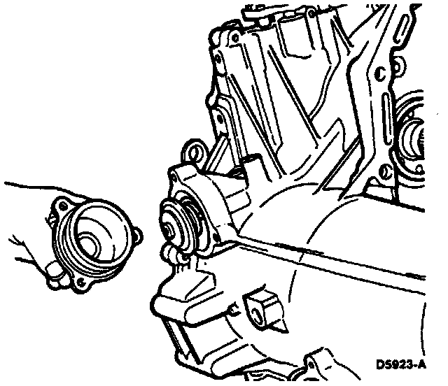
Align Tab On Servo Cover:
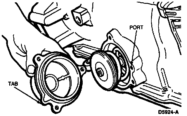
91 Install servo covers for overdrive and low/intermediate servo using new gaskets and seals. Tighten bolts evenly to 9-12 Nm (7-9 ft-lb).
CAUTION: Tighten bolts two or three turns at a time to prevent misalignment of servo covers.
NOTE: Be sure to align tab on servo cover with port or case.
Speedometer Drive Gear Components:

92. Install speedometer driven gear retainer and shaft. Install speedometer drive gear and shaft making sure that slots in gear align with roll pin in shaft. Install speedometer thrust bearing and race with black side up.
Speedometer Cover And Components:

93. Install speedometer cover with new seal. Tighten bolts to 9-12 Nm (7-9 ft-lb).
Filler Tube Retaining Bolt:

94. Install level indicator seal onto fluid level indicator, then install fluid level indicator into filler tube. Attach filler tube to case. Tighten bolt to 9-12 Nm (7-9 ft-lb).
95. Install torque converter.