Intake Manifold: Service and Repair
NOTE: Ford does not provide a TDC (Top Dead Center) mark or determination procedure for this engine in this vehicle.
ALLDATA users have reported success using aftermarket tools to determine TDC on this engine.
REMOVAL AND INSTALLATION
NOTE: The upper intake manifold is removed as an assembly with the throttle body.
1. Disconnect battery ground cable and set aside, then drain engine cooling system.
2. Remove PCV closure hose from valve cover and air cleaner outlet tube, then the air cleaner outlet tube from throttle body and engine air cleaner.
3. Relieve fuel pressure.
4. Remove fuel tube clips, then disconnect fuel supply and return lines.
5. Mark location of vacuum lines and remove.
6. Disconnect Intake Air Temperature (IAT) sensor, Idle Air Control (IAC) valve and Engine Coolant Temperature (ECT) sensor electrical connectors.
7. Disconnect distributor, ignition coil and radio ignition interference capacitor electrical connectors.
8. Disconnect water temperature indicator sender unit, EGR pressure sensor and EGR vacuum regulator control electrical connectors.
9. Disconnect upper radiator hose from water hose connection by loosening hose clamp, then twist hose from housing.
10. Remove throttle body as follows:
a. Remove engine air cleaner intake tube and duct between air cleaner and throttle body by loosening clamps.
b. Remove three plastic push retainers attaching fuel supply manifold shield to power steering pump bracket and accelerator cable bracket, then the shield.
c. Mark and disconnect PCV hose and vacuum hoses at vacuum fittings on intake manifold.
d. Disconnect and remove accelerator and speed control cables from accelerator mounting bracket and throttle lever.
e. Remove alternator brace, then the wiring harness connector at throttle position sensor, intake air temperature sensor and idle air control valve.
f. Remove throttle body to intake manifold bolts and stud bolts, then lift throttle body from intake manifold.
g. Remove and discard gasket from intake manifold.
11. Disconnect fuel charging wiring retaining standoffs from inboard rocker arm cover studs. Carefully disconnect electrical connections to each fuel injector and remove harness from engine.
12. Disconnect heater water hoses, then remove spark plug wire set from spark plugs, using twisting motion on rubber boots.
13. Remove harness retaining standoffs from rocker arm cover studs.
14. Remove spark plug from No. 1 cylinder and bring piston to Top Dead Center (TDC) on compression stroke.
15. Mark distributor housing to cylinder block and note rotor position, then remove distributor bolt, clamp and distributor.
16. Remove coil and bracket assembly from rear of left cylinder head.
17. Remove valve covers.
18. Loosen No. 3 cylinder intake valve rocker arm bolt and rotate rocker arm off push rod and away from top of valve stem, then remove push rod.
19. Remove intake manifold bolts using Torx head socket, then the intake manifold, noting the following:
a. Intake manifold may be removed with fuel injector and fuel injection supply manifolds in place.
b. Before removing intake manifold, break seal between intake manifold and cylinder block.
c. Wedge large screwdriver or similar heavy duty tool between manifold and block, then pry upward on tool using lug on top of front cover as leverage point.
d. Remove alternator.
e. Use care to prevent damage to machined surfaces.
20. Reverse procedure to install, noting the following:
a. Lightly oil all bolt and stud threads before installing.
b. Clean mating gasket surfaces of intake manifold and cylinder block, laying clean cloth or shop rag in tappet valley to catch any gasket material. After scraping, carefully lift cloth from tappet valley, preventing any particles from entering oil drain holes or cylinder head. Use suitable solvent to remove old rubber sealant.
c. Aluminum components gouge easily which may cause gasket to leak.
NOTE: Always use care when scraping aluminum gasket surfaces.
Fig. 4 Intake Manifold Installation.:
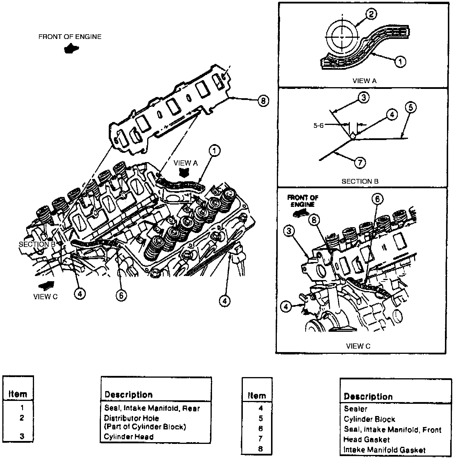
d. Apply 0.197 to 0.236 in drop of silicone rubber part No. D6AZ-19562-AA or -BA, or equivalent, to intersection of cylinder block and cylinder head at four corners.
e. Position intake manifold gaskets onto cylinder heads, aligning intake gasket locking tabs to provisions on cylinder head gaskets.
Fig. 3 Intake Manifold Bolt Tightening Sequence:

f. Torque intake manifold bolts in sequence, first to 11 ft lb, then to 19-24 ft lb.
g. Dip entire distributor drive gear in Engine Assembly Lubricant D9AZ-19579-D or equivalent.
NOTE: If new distributor or camshaft position sensor is installed, be sure to add rest of pint of engine assembly lubricant part No. D9AZ-19579-D or equivalent, to engine oil by pouring through distributor side hole onto cam drive gear. Run engine at idle for five minutes before driving vehicle.