Disassembly and Assembly
DISASSEMBLY1. Remove flywheel and engine rear plate.
NOTE: Before starting disassembly, remove accessories and any emission control equipment which is not directly attached to engine.
2. Remove exhaust manifolds.
NOTE: When LH exhaust manifold is removed, note location of oil level indicator tube support bracket.
3. Remove following positive crankcase ventilation system components:
a. Front and rear crankcase ventilation tube.
b. Positive crankcase ventilation valve (PCV valve).
c. Crankcase ventilation grommet.
4. Remove water bypass tube.
5. Disconnect ignition wires from spark plugs.
NOTE: When removing an ignition wire from a spark plug, use Spark Plug Wire Remover T74P-6666-A. Grasp and twist boot back and forth on plug insulator to free boot. Use tool to pull boot from plug. Do not pull on ignition wire directly or it may become separated from the connector inside the boot.
6. Remove camshaft position sensor (CMP sensor) and camshaft position sensor housing.
7. Remove the upper intake manifold.
8. Remove intake manifold upper gasket.
9. Remove fuel injection supply manifold.
10. Remove crankshaft pulley and vibration damper. Use Crankshaft Damper Remover T58P-6316-D and Vibration Damper Remover Adapter T82L-6316-B to remove vibration damper.
11. Remove valve covers.
12. Remove lower intake manifold and intake manifold gaskets. Discard intake manifold gaskets and end seals.
CAUTION: Use care to prevent damage to machined surfaces or possible leakage may occur upon reassembly.
NOTE: Before attempting to remove lower intake manifold, break seal between intake manifold and cylinder block. Wedge a large prybar between intake manifold and cylinder block. Pry downward on prybar using lug on water pump as a leverage point.
13. Remove spark plugs.
14. Remove rocker arms and push rods.
NOTE: The location of each rocker arm push rod and rocker arm seat should be noted. When engine is assembled each component should be installed in its original location.
15. Remove cylinder heads. Discard cylinder head retaining bolts. Remove and discard head gaskets.
16. Remove valve tappets, valve tappet guide plate and tappet guide plates and retainers.
NOTE: If valve tappets are stuck in bores due to excessive varnish or gum deposits, it may be necessary to use a magnet or a claw-type tool to aid removal. When using a remover tool, rotate valve tappet back and forth to loosen it from any gum or varnish that may have formed on valve tappet. The location of each valve tappet should be identified. When engine is assembled each valve tappet should be installed in its original location.
17. Remove oil bypass filter and engine oil cooler (if equipped).
18. Remove oil pan.
19. Remove oil pump screen cover and tube. Discard oil pump inlet tube gasket.
20. Remove water pump and engine front cover as an assembly. Remove and discard engine front cover gasket.
NOTE: If necessary, water pump can be removed from engine front cover. Discard water pump housing gasket after removal.
21. Remove camshaft sprocket retaining bolt and washer from end of camshaft.
22. Remove distributor drive gear.
Distributor Gear:
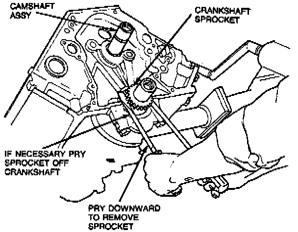
23. Remove camshaft sprocket, crankshaft sprocket, timing chain and timing chain vibration damper.
CAUTION: Use care to prevent damage to finished areas on crankshaft and crankshaft sprocket or component failure may occur.
NOTE: If crankshaft sprocket is difficult to remove, it can be loosened using two large pry bars.
24. Remove engine balance shaft drive gear.
25. Remove camshaft thrust plate.
26. Remove camshaft. Use care to prevent damage to camshaft bearing surfaces.
27. If necessary, remove camshaft rear bearing cover from back of cylinder block.
28. Remove screws securing balance shaft thrust plate.
29. Remove balance shaft gear, balance shaft thrust plate and engine dynamic balance shaft.
CAUTION: Use care to prevent damage to bearing surface as possible bearing failure may occur.
30. Remove connecting rod caps and install connecting rod guide tool over connecting rod bolt holes and push piston out through the top of the cylinder bore. Use care to prevent damage to crankshaft bearing surface(s).
NOTE: Before removing pistons, inspect top of cylinder bores. If necessary, remove ridge and/or carbon deposits from each cylinder using Rotunda Cylinder Ridge Reamer 014-00292 or equivalent. Before ridge or deposits are removed, turn crankshaft until piston is at bottom of its stroke. Cover piston with a clean shop towel to collect cuttings. After cutting operation, turn crankshaft until piston is at top of its stroke and remove shop towel with cuttings.
CAUTION: Never cut into ring travel area in excess of 0.794mm (0.0325 inch) or damage to the cylinder block may occur.
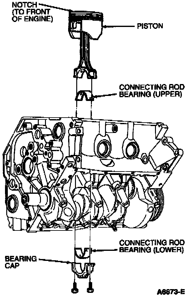
31. Mark the location of each piston, connecting rod bearing and connecting rod cap. When engine is assembled each component should be installed in its original position.
32. Remove crankshaft main bearing caps and crankshaft.
33. Mark the location of crankshaft main bearings. When engine is assembled each crankshaft main bearing should be installed in its original position.
34. Clean and inspect pistons, connecting rods, crankshaft and cylinder block. Refinish or replace components as required.
NOTE: For cleaning purposes, oil gallery and cooling jacket plugs can be removed.
ASSEMBLY
1. If removed, install oil gallery and cooling jacket plugs. To provide clearance for camshaft sprocket, oil gallery plugs on front of engine must be threaded below machined surface. Tighten plugs to specification.
NOTE: During engine assembly, a sealer will be applied to many components before installation. When the sealant is applied, the component should be installed within 15 minutes. After this time the sealant begins to set-up and its sealing effectiveness can be reduced. Lightly oil all retaining bolt and stud bolt threads before installation except those specifying special sealant with clean engine oil meeting Ford specification ESE-M2C153-E. Before installation, coat plug threads with Pipe Sealant with Teflon(R) D8AZ-19554-A or equivalent meeting Ford specification WSK-M2G350-A2.
2. Install crankshaft as follows:
a. Install crankshaft main bearings in cylinder block. Note that third bearing from front is the crankshaft thrust main bearing.
b. Lubricate crankshaft main bearings with Engine Assembly Lubricant D9AZ-19579D or equivalent meeting Ford specification ESR-M99C80-A, or heavy engine oil, and carefully lower crankshaft into place. Use care to prevent damage to crankshaft main bearing surfaces.
c. Apply a 3 mm (0.125 inch) bead of Silicone Rubber, D6AZ-19562-AA or BA or equivalent meeting Ford specifications ESB-M4G92-A and ESE-M4G 195-A to cylinder block rear main bearing cap parting line.
d. Install crankshaft main bearings in main bearing caps and install caps. Note that caps are numbered with triangles. Number one is located at front of engine with triangle facing front of engine.
e. Install main bearing cap retaining bolts.
f. Before tightening main bearing cap bolts wedge a large pry bar between cylinder block web and crankshaft cheek located in front of No. 3 crankshaft main bearing. Do not jam pry bar into place. Tap into position only enough to hold crankshaft forward while main bearing cap bolts are tightened.
g. Tighten main bearing cap retaining bolts to 110-120 Nm (81-88 ft. lbs.) and remove pry bar.
3. Check crankshaft end play.
4. Install pistons as follows:
a. Install connecting rod bearings in connecting rods and connecting rod caps.
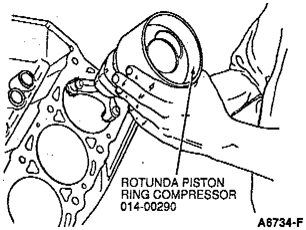
b. Install pistons and upper connecting rod bearings using Rotunda Piston Ring Compressor 014-00290 or equivalent. The stamped arrow in piston dome must face front of engine.
NOTE: Lubricate piston and cylinder walls with Engine Assembly Lubricant D9AZ-19579D or equivalent meeting Ford specification ESR-M99C80-A, or engine oil before installation. Scratching of crankshaft journal can be prevented by using connecting rod guide tool on connecting rod.
c. Install connecting rod caps, lower connecting rod bearings and retaining nuts. Tighten bolts to 40 Nm (29 ft. lbs.). Rotate nuts an additional 90-120 degrees.
5. Check connecting rod side clearance.
6. Coat sealing edge of camshaft rear bearing cover with Perfect-Seal Sealing Compound B5A-19554-A or equivalent meeting Ford specifications ESR-M18P2-A and ESE-M4G115-A before installation.
7. Install camshaft rear bearing cover using a suitable driver.
8. Coat camshaft lobes and camshaft bearings with Engine Assembly Lubricant D9AZ-19579D or equivalent meeting Ford specification ESR-M99C80-A,

9. Install camshaft.
10. Install spacer and camshaft thrust plate.
NOTE: Camshaft spacer must be installed prior to key on camshaft. Both should be done prior to camshaft installation.
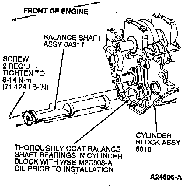
11. Install balance shaft, balance shaft thrust plate and gear as an assembly, and tighten retaining bolts to 8-14 Nm (71-124 inch lbs.).
12. Install engine balance shaft drive gear. Align balance shaft timing marks as shown.
13. Lubricate timing chain with clean engine oil XO-10W30-QSP or -DSP or equivalent meeting Ford specification ESE-M2C153-E.
14. Rotate crankshaft as necessary to position crankshaft keyway in 12 o'clock position. Install timing chain tensioner (retracted position).
15. Install camshaft sprocket, crankshaft sprocket and timing chain simultaneously. Pull pin on timing chain tensioner to release timing chain tensioner against chain.
NOTE: Do not remove pin at this time.
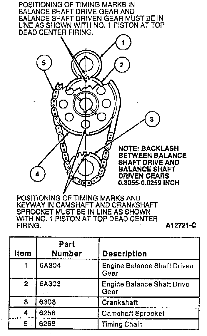
16. Make sure crankshaft keyway, camshaft sprocket timing mark and crankshaft sprocket timing mark are properly aligned after installation.
17. Install camshaft position sensor drive gear.
18. Install camshaft sprocket retainer bolt and washer and tighten to 40-50 Nm (29-37 ft. lbs.).
19. If water pump was removed from engine front cover during engine disassembly, position a new water pump housing gasket on engine front cover and install water pump. Tighten water pump retaining bolts to 20-30 Nm (15-22 ft. lbs.).
20. Position a new engine front cover gasket on engine. Install engine front cover. Tighten attaching bolts to 20-30 Nm (15-22 ft. lbs.).
21. Install oil pump screen cover and tube using a new oil pump inlet tube gasket. Tighten retaining bolts to 20-30 Nm (15-22 ft. lbs.), and support bracket retaining nut to 40-55 Nm (29-40 ft. lbs.).
22. Install oil pan as follows:
a. Using a small-blade screwdriver remove any sealer which may have been squeezed into seal groove when rear main bearing cap was installed. Place a 6.35 mm (0.25 inch) bead of Silicone Rubber D6AZ-19562-AA or -BA or equivalent meeting Ford specifications ESB-M4G92-A and ESE-M4B195-A, into seal groove where bearing cap meets cylinder block.
NOTE: Prior to applying sealer, clean oil pan and cylinder block sealing surfaces with Metal Surface Cleaner F4AZ-19A536-RA or equivalent meeting Ford specification WSE-M5B392-A, to remove all residues that may interfere with the sealer's ability to adhere.
b. Apply a 3 mm (0.125 inch) bead of Silicone Gasket and Sealant Sealer D6AZ-19562-AA or BA or equivalent meeting Ford specifications ESB-M4G92-A and ESE-M4G195-A to seams where engine front cover mates with cylinder block and to each end of oil pan end seal.
c. Apply a 3 mm (0.125 inch) bead of Silicone Gasket and Sealant D6AZ-19562-AA or BA or equivalent meeting Ford specifications ESB-M4G92-A and ESE-M4G195-A in a zig-zag pattern to the oil pan sealing surface.
d. Install oil pan. Tighten retaining bolts to 9-12 Nm (80-106 inch lbs.).
23. Install engine oil cooler (if equipped) and lubricate oil bypass filter gasket with clean engine oil meeting Ford specification ESE-M2C153-E and install oil bypass filter onto oil pump and filter body until gasket contacts oil pump and filter body, then tighten oil bypass filter an additional one-half turn.
24. Lubricate valve tappets with Engine Assembly Lubricant D9AZ-19579-D or equivalent meeting Ford specification ESR-M99C80-A, and install valve tappets. Install valve tappet guide plate and tappet guide plates and retainers.
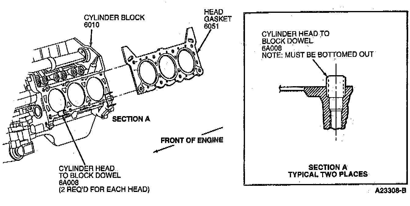
25. Install new head gaskets using cylinder head to block dowels to align head gasket.
26. Position cylinder heads onto cylinder block.
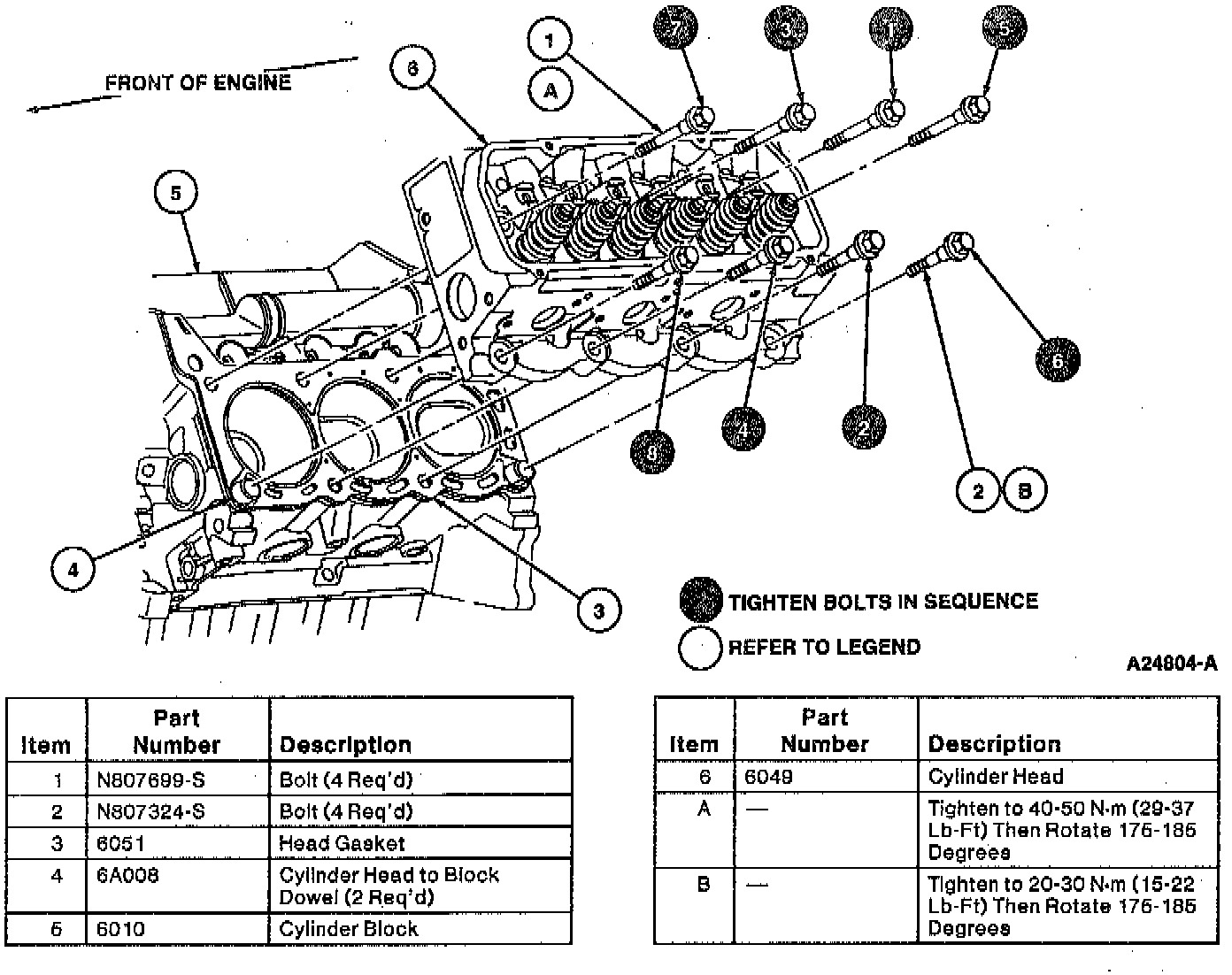
27. Install cylinder bolts (eight each side).
CAUTION: Always use new cylinder head bolts to make sure a leak-tight assembly. Torque retention with used bolts can vary which may result in coolant or compression leakage at the cylinder head mating surface area.
28. Tighten cylinder head retaining bolts in sequence as follows.
a. 20 Nm (15 ft. lbs.)
b. 40 Nm (30 ft. lbs.)
c. 50 Nm (37 ft. lbs.)
NOTE: When cylinder head retaining bolts have been tightened using the recommended procedure, it is not necessary to retighten bolts after extended engine operation. However, bolts can be checked for tightness if desired.
29. In sequence, loosen retaining bolts two or three revolutions and retighten bolts in the following manner:
a. Long bolts:
- 40-50 Nm (29-37 ft. lbs.).
- Tighten an additional 175-185 degrees.
- Go to the next bolt in sequence.
b. Short bolts:
- 20-30 Nm (15-22 ft. lbs.).
- Tighten an additional 175- 185 degrees.
- Go to next bolt in sequence.
CAUTION: Do not loosen all of the bolts at the same time, only work on one bolt at a time.
30. Install push rods, rocker arms, rocker arm seats and retaining bolts.
NOTE: Lubricate push rod ends, rocker arm seats and rocker arms with Engine Assembly Lubricant D9AZ-19579-D or equivalent meeting Ford specification ESR-M99C80-A, or heavy engine oil before installation.
31. For each exhaust valve or intake valve, rotate crankshaft until valve tappet rests on heel (base circle) of camshaft lobe. Tighten rocker arm seat retaining bolt to 5 Nm (44 inch lbs.). Final tighten the rocker arm seat retaining bolts to 30-40 Nm (22-29 ft. lbs.). For final tightening, camshaft may be in any position.
NOTE: If original valve train components are being installed, a valve clearance check is not required. If a component has been replaced, perform a valve clearance check.
32. Install lower intake manifold.
33. Install spark plugs.
34. Install valve covers as follows:
35. Install a new valve cover gasket onto valve cover.
NOTE: Using solvent, clean valve cover and cylinder head sealing surfaces to remove all gasket material and dirt.
36. Install valve cover and retaining bolts. Note location of stud bolts. Tighten to 9-12 Nm (80-106 inch lbs.).
37. Install camshaft position sensor housing and camshaft position sensor.
38. Install vibration damper using Damper/Front Cover Seal Replacer T82L-6316-A and Front Cover Seal Replacer T70P-6B070-A. Tighten retaining bolt to 140-180 Nm (103-132 ft. lbs.).
39. Install crankshaft pulley onto vibration damper. Tighten retaining bolts to 26-38 Nm (19-29 ft. lbs.).
40. Install fuel injector and fuel injection supply manifold.
41. Install crankcase ventilation tube and positive crankcase ventilation valve.
42. Install upper intake manifold.
43. Connect ignition wires to spark plugs.
44. Install water bypass tube. Tighten retaining bolt to 8-12 Nm (71-106 inch lbs.).
45. install exhaust manifolds.
46. Install engine rear plate and flywheel. Tighten retaining bolts to 73-87 Nm (54-64 ft. lbs.) in standard cross-tightening sequence.
NOTE: Apply a thin coat of Pipe Sealant with Teflon(R) D8AZ-19554-A or equivalent meeting Ford specifications WSK-M2G350-A2 and ESR-M 18P7-A to flywheel retaining bolt threads before installation.