Disassembly
SPECIAL SERVICE TOOL(S) REQUIREDTorque Converter Handles: T81P-7902-C
Bench Mounted Holding Fixture: T57L-500-B
Front Cover Seal Remover: T74P-6700-A
Converter Seal Remover: T94P-77001-BH
Lube Tube Remover: T94P-77001-CH
Impact Slide Hammer: T50T-100-A
Bearing: T94P-77001-KH
O-Ring Remover: T71P-19703-C
Front Clutch Loading Tool: T86P-70389-A
Installing Torque Converter Handles:

1. Install Torque Converter Handles T81P-7902-C. Remove torque converter from transaxle.
CAUTION: The torque converter is heavy. Be careful not to drop it.
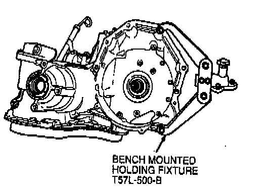
2. Mount transaxle in Bench Mounted Holding Fixture T57L-500-B.
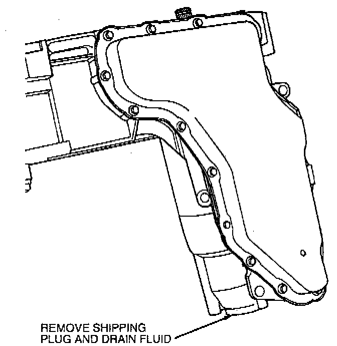
3. Turn transaxle in vertical position and drain fluid.
4. Return transaxle to horizontal position.
Speedometer Cover And Components:

5. Remove two 8 mm cover bolts, speedometer cover and seal. Discard seal. A new one must be installed during assembly.
Speedometer Drive Gear Components:

6. Lift speedometer drive gear and shaft and speedometer thrust bearing and race out of case.
NOTE: Bearing sits on top of speedometer drive gear and shaft.
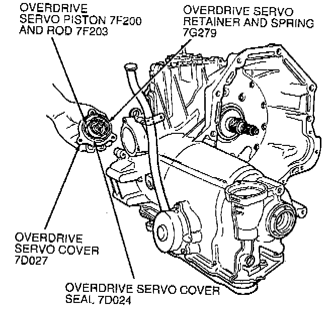
7. Remove three 8 mm overdrive servo cover bolts remove servo cover, piston and spring assembly and discard servo cover seal.
CAUTION: The overdrive band servo spring retainer is under spring tension. Care must be taken when removing.
NOTE: Piston assembly and spring may remain in cover.
Low/Intermediate Servo Components:

8. Remove three 8 mm low/intermediate servo cover bolts, low/intermediate servo cover, servo band piston and servo piston spring.
CAUTION: The low/intermediate servo cover is under spring tension. Care must be taken when removing.
NOTE: Piston assembly and spring may remain in cover.
9. Remove and discard low/intermediate servo cover seal and gasket.
10. Inspect RH differential seal and replace if damaged. Remove as follows:
NOTE: Differential shaft seal is a two-piece construction, outer metal protector and inner rubber seal.
RH Differential Shaft Seal:

a. Install Step Plate Adapter D80L-630-3 or equivalent into output shaft opening. Use grease to hold tool in place.
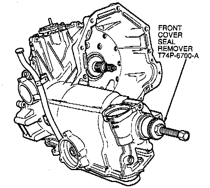
b. Screw Front Cover Seal Remover T74P-6700-A into metal seal protector.
c. Tighten screw on end of tool until metal seal protector is removed.
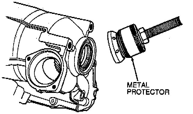
d. Remove metal protector from tool, and install tool into seal.

e. Tighten screw on the end of tool until seal is removed.
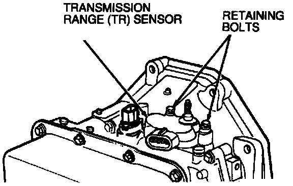
11. Remove two 8 mm Transmission Range (TR) sensor retaining bolts and remove sensor.
Filler Tube Retaining Bolt:

12. Remove one 8 mm filler tube retaining bolt and pull fluid filler tube and grommet from case.
Chain Cover Bolts:

13. Remove five 10 mm and four 8 mm chain cover bolts from inside converter housing.
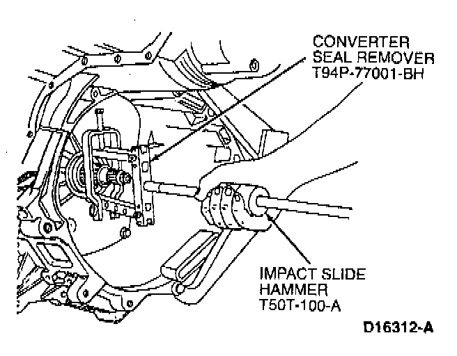
14. Remove and discard converter impeller hub seal using Converter Seal Remover T94P-77001-BH and Impact Slide Hammer TOOT-100-A.
CAUTION: Do not damage any machined surfaces.
15. Rotate transaxle to vertical position.
Servicing Pump/Valve Body Cover Bolts:

16. Remove twelve 10 mm pump assembly and valve body cover (upper reservoir) bolts. Using an 8 mm socket, remove main control cover and main control cover gasket.
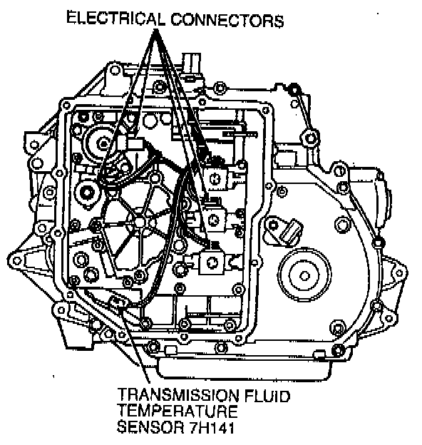
17. Disconnect electrical connectors from Transmission Fluid Temperature (TFT) sensor and solenoids. Remove wire retaining clip from pump body separating plate.
CAUTION: Use both hands. Do not pull on wires.
Rotating Manual Control Lever Shaft:

18. Using a 9 mm wrench on flats on end of manual control lever shaft, rotate shaft clockwise to position manual linkage in LOW detent (valve positioned all the way in).
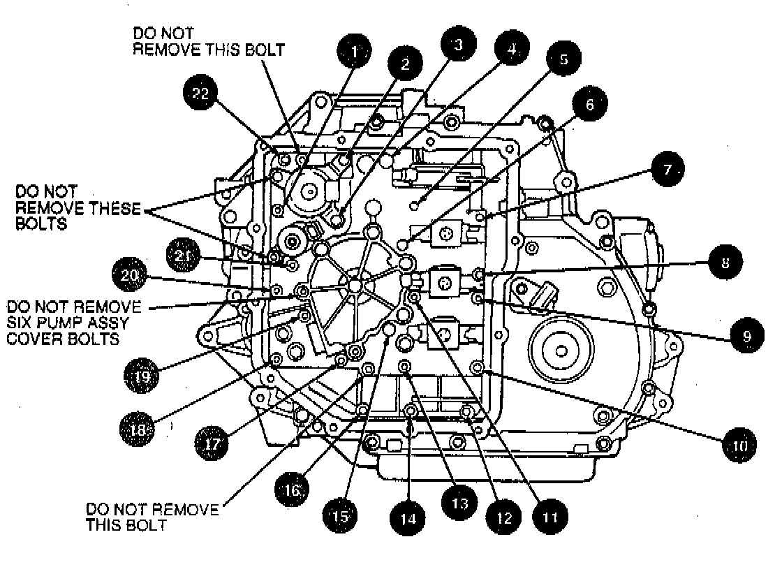
19. Remove twenty-two 8 mm pump assembly and main control valve body assembly retaining bolts. Note length and location of bolts.
CAUTION:
^ Do not remove the two bolts that retain the pump assembly and valve body assembly together.
^ Do not remove pump assembly cover bolts.
Rotating Valve Body:

20. Rotate main control valve body clockwise. Remove manual valve link from manual valve and remove main control valve body.
21. Disconnect manual valve link from manual valve detent lever.
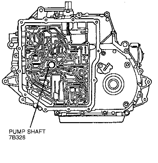
22. Pull pump shaft out of case.
Output Shaft Circlip:

23. Remove output shaft circlip. Inspect and replace if necessary.
Servicing LH Differential Seal:

24. Remove LH differential seal as follows:
a. Screw Front Cover Seal Remover T74P-6700-A into metal seal protector.
b. Tighten screw on the end of tool until metal seal protector is removed.
c. Remove metal seal protector from tool and install tool into seal.
d. Tighten screw on end of tool until seal is removed.
Turbine Shaft Speed Sensor:

25. Remove 8 mm bolt and Turbine Shaft Speed (TSS) sensor.
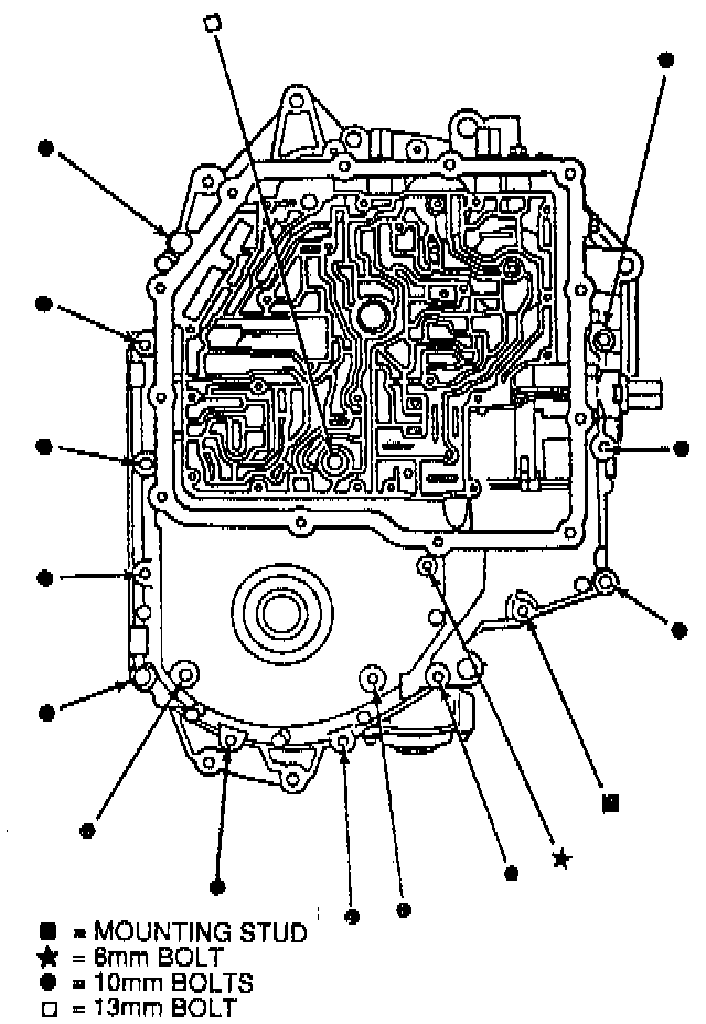
26. Remove thirteen 10 mm, one 13 mm and one 8 mm bolt, and one 24 mm mounting stud. Note length and location of bolts. Start at inside and work out.
CAUTION: Chain cover is under spring pressure. Use care when removing.
Accumulator Springs:

27. Remove chain cover and tag accumulator springs to be sure they are installed in their correct positions during assembly. Remove and discard chain cover gasket.
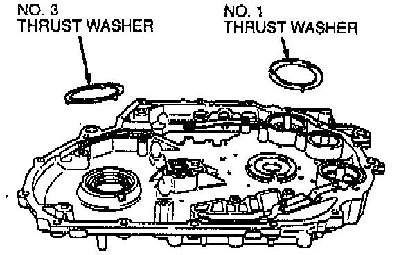
28. Remove No. 1 and No. 3 thrust washers from chain cover.
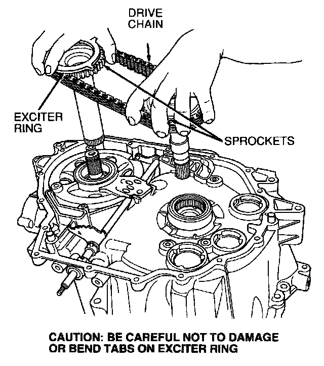
29. Simultaneously, lift out both drive sprocket and driven sprocket with drive chain.
CAUTION: Be careful not to damage or bend tabs on exciter ring.
No. 2 & No. 4 Thrust Washers:

30. Remove No. 2 thrust washer from drive sprocket support and No. 4 thrust washer from driven sprocket support.
NOTE: Thrust washers may remain on driven sprocket.
Drive Sprocket Bearing:

31. Inspect drive sprocket bearing to determine if it needs to be replaced.
Drive Sprocket Bearing Removal:

32. IF NECESSARY, remove drive sprocket bearing using Puller T50T-100-A and Bearing Remover T94P-77001-KH.
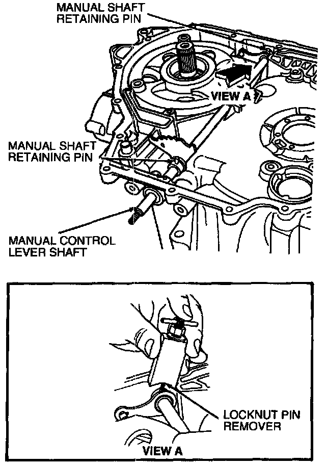
33. Remove and discard three roll-pins from manual control lever shaft using Locknut Pin Remover D81P-3504-N or equivalent.
CAUTION: Use care not to damage any machined surfaces.
Manual Control Shaft Removal:

Removing Manual Control Shaft Seal:
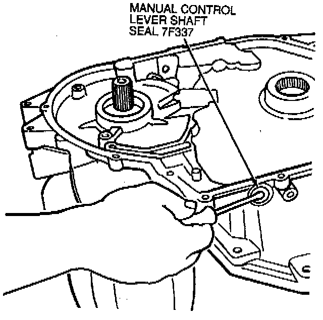
34. Slide manual control lever shaft out of case and remove manual detent lever. Then, pry manual control lever shaft seal out of case.
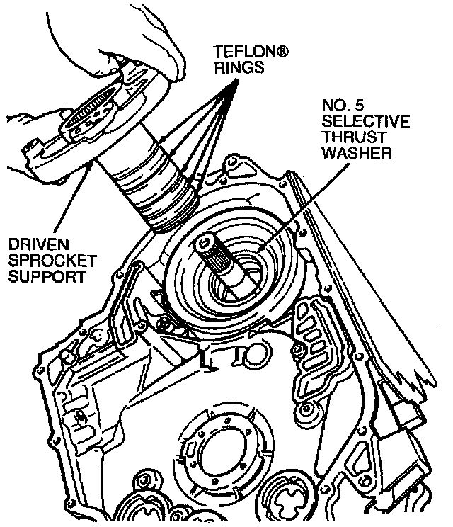
35. Remove driven sprocket support and remove No. 5 selective thrust washer.
NOTE: Thrust washer may remain on driven sprocket support.
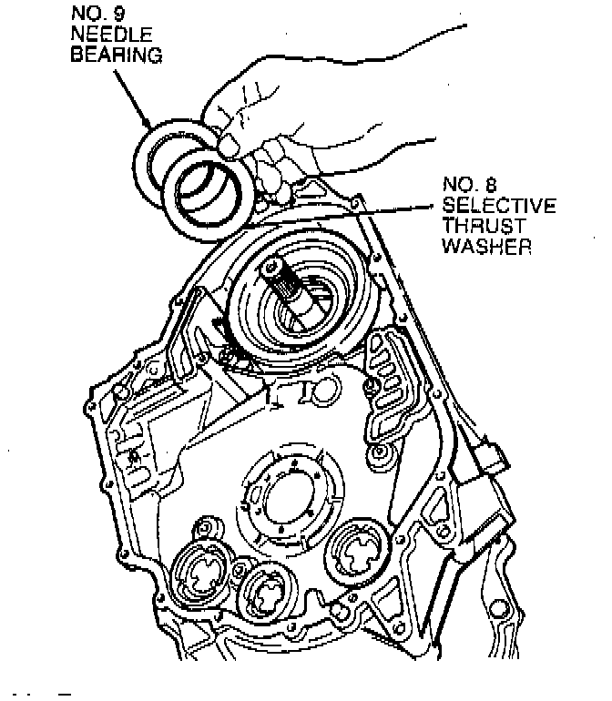
36. Using O-Ring Remover T71P-19703-C, remove No. 8 selective thrust washer and No. 9 needle bearing from bottom of cylinder.
NOTE: Thrust washer and driven sprocket bearing may remain on driven sprocket support when it is removed.
Overdrive Band Anchor Strut:

37. Remove plastic overdrive band anchor strut.
Overdrive Band:

38. Remove overdrive band. Remove screen filter and clean with moisture-free compressed air.
39. Rotate transaxle to horizontal position with transaxle pan up.
Transmission Pan:

40. Using an 6 mm socket, remove seventeen pan cover bolts. Remove cover and pan-to-case gasket.
Transmission Pan Magnet:

41. Remove magnet from transaxle pan.
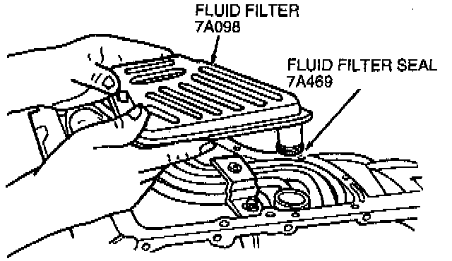
42. Remove fluid filter screen and discard fluid filter seal.
NOTE: Lip seal may stick inside case.
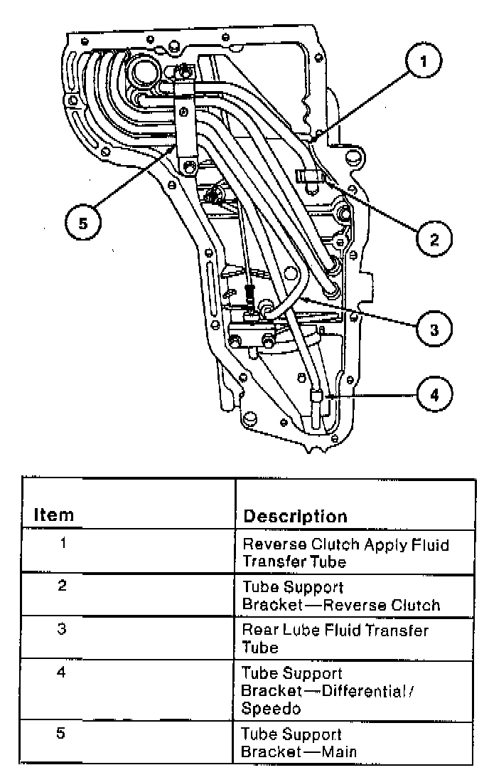
43. Remove four 8 mm tube bracket bolts, one retainer screw and tube support brackets.
NOTE:
^ For complete transaxle disassembly, the reverse clutch apply fluid transfer tube and the rear lube fluid transfer tube must be removed and discarded prior to removing the reverse clutch or differential.
^ All fluid transfer tubes removed from the case must be discarded and replaced with new tubes. The tubes become distorted during removal and will not seal properly when reinstalled. The new tubes have a press fit and are not distorted from prior removal and installation. Do not remove tubes unless it is necessary to service the transaxle. Do not replace the tubes unless they have been removed for servicing. Replace any tubes removed from the case.
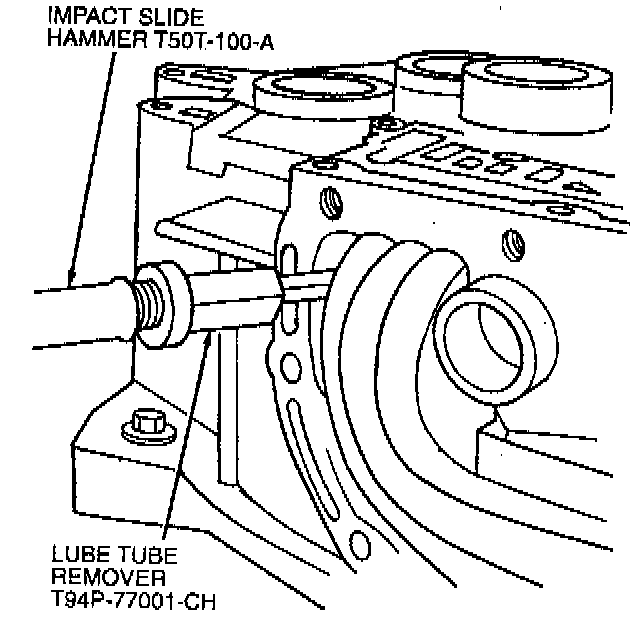
44. Remove and discard lube tubes using Lube Tube Remover T94P-77001-CH and Impact Slide Hammer T50T-100-A.
Parking Lever Actuating Rod:

45. Remove two 10 mm parking lever actuating rod support bolts. Remove support. Remove parking lever actuating rod.
46. Using Locknut Pin Remover D81P-3504-N or equivalent, remove parking pawl shaft roll pin.
Parking Pawl Shaft:

47. Use magnet to remove parking pawl shaft. Remove parking pawl and parking pawl return spring.

48. Rotate transaxle to vertical position. Using Front Clutch Loading Tool T86P-70389-A, install hook end of tool into one of the six lube holes in front sun and shell. Position notched block over edge of assembly and tighten handle. Do not over-tighten handle. Lift assembly out of case.
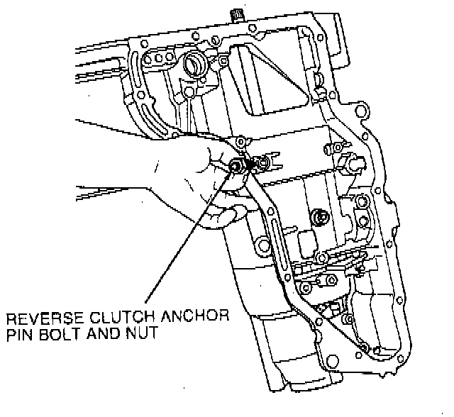
49. Loosen 19 mm reverse clutch anchor pin nut and remove 6 mm Allen-head bolt.
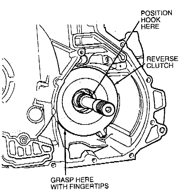
50. Locate hook portion of Front Clutch Loading Tool T86P-70389-A on inner diameter of reverse clutch hub. Grasp outer diameter of cylinder with fingertips and slide reverse clutch out of case.
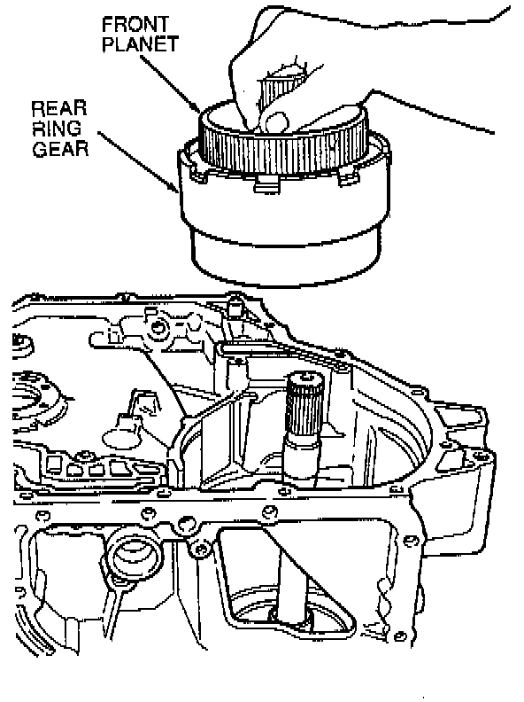
51. Holding the front planet shaft, lift out both front planet and rear ring gear.
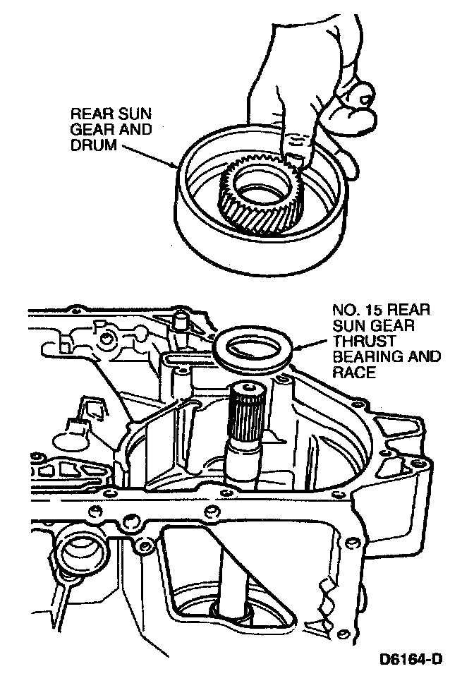
52. Lift out rear sun gear and drum and remove No. 15 rear sun gear thrust bearing and race.
NOTE: The No. 15 rear sun gear thrust bearing and race may adhere to the bottom of the rear sun gear and drum.

53. Remove low and intermediate band.
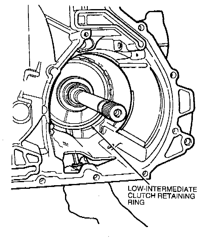
54. Remove rear support snap ring from case using a screwdriver inserted through side of case.
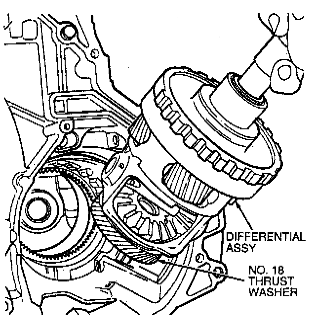
55. Lift out differential assembly using output shaft.
No. 18 Thrust Washer And No. 19 Needle Bearing:

56. Remove No. 18 thrust washer and No. 19 needle bearing.
NOTE: No. 18 thrust washer may remain on the differential assembly next to speedometer drive gear.
Final Drive Ring Gear:

57. Remove final drive ring gear from case.
Stator Support:

58. If case replacement is necessary, rotate case 180 degrees and remove six T-30 Torx bolts retaining stator support to case.