Ignition Switch Diode 2
Ignition Switch Diode 1
Inline Connector C1023 is at the Engine Compartment Fuse Box.
Connector: C1023, Color = 'BK', Terminal= '2'
Ignition Switch Diode 2
Inline Connector C2012 is at the Interior Fuse Panel.
Connector: C2012, Color = 'BK', Terminal= '2'
There are no connector views for the C1023 or C2012 given. Refer to the wiring diagram. Electrical Diagrams
There are nearby connectors shared between the Ignition Switch Diode 2 and the Fuse Box; the Ignition Relay and the Central Timer Module:
Interior Fuse Panel:
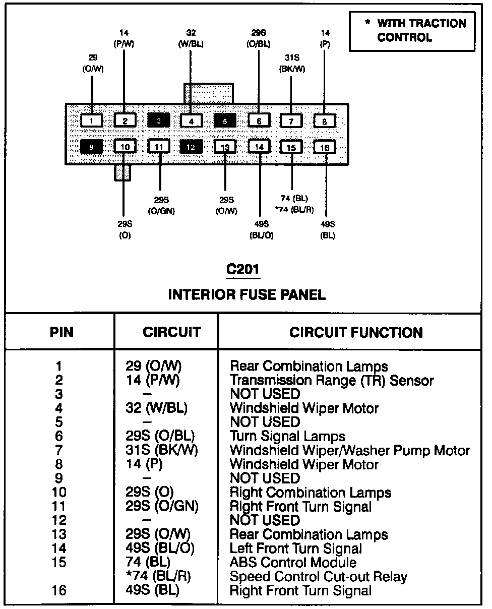
Connector: C201, Color = 'BK', Terminal= '10'
Interior Fuse Panel:
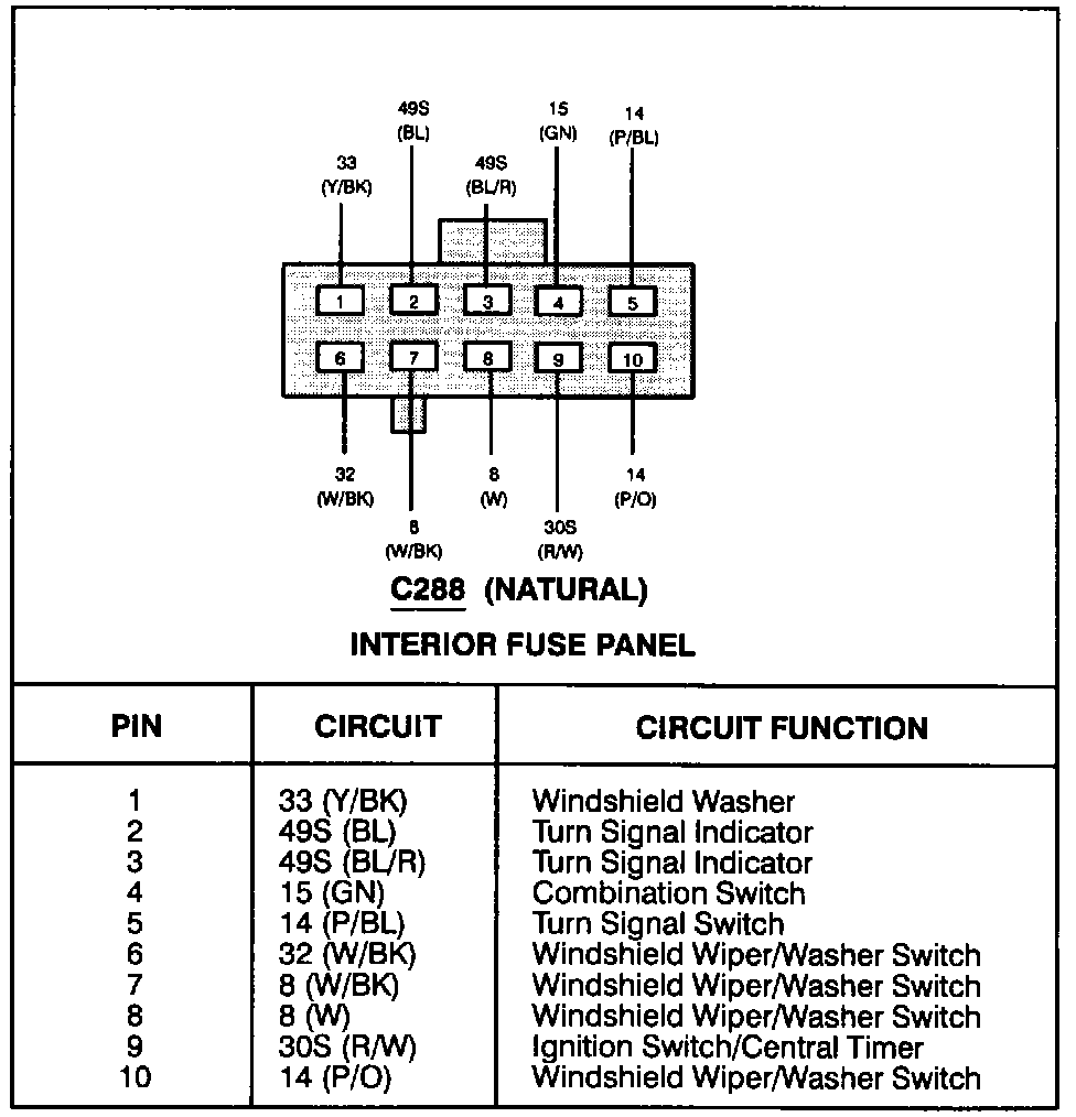
Connector: C288, Color = 'NAT', Terminal= '10'
Interior Fuse Panel
Connector: C2011, Color = 'BK', Terminal= '5'
Ignition Relay (no connector view for C2011 refer to the Power Distribution wiring for Circuit breaker 20) Electrical Diagrams
Central Timer Module:
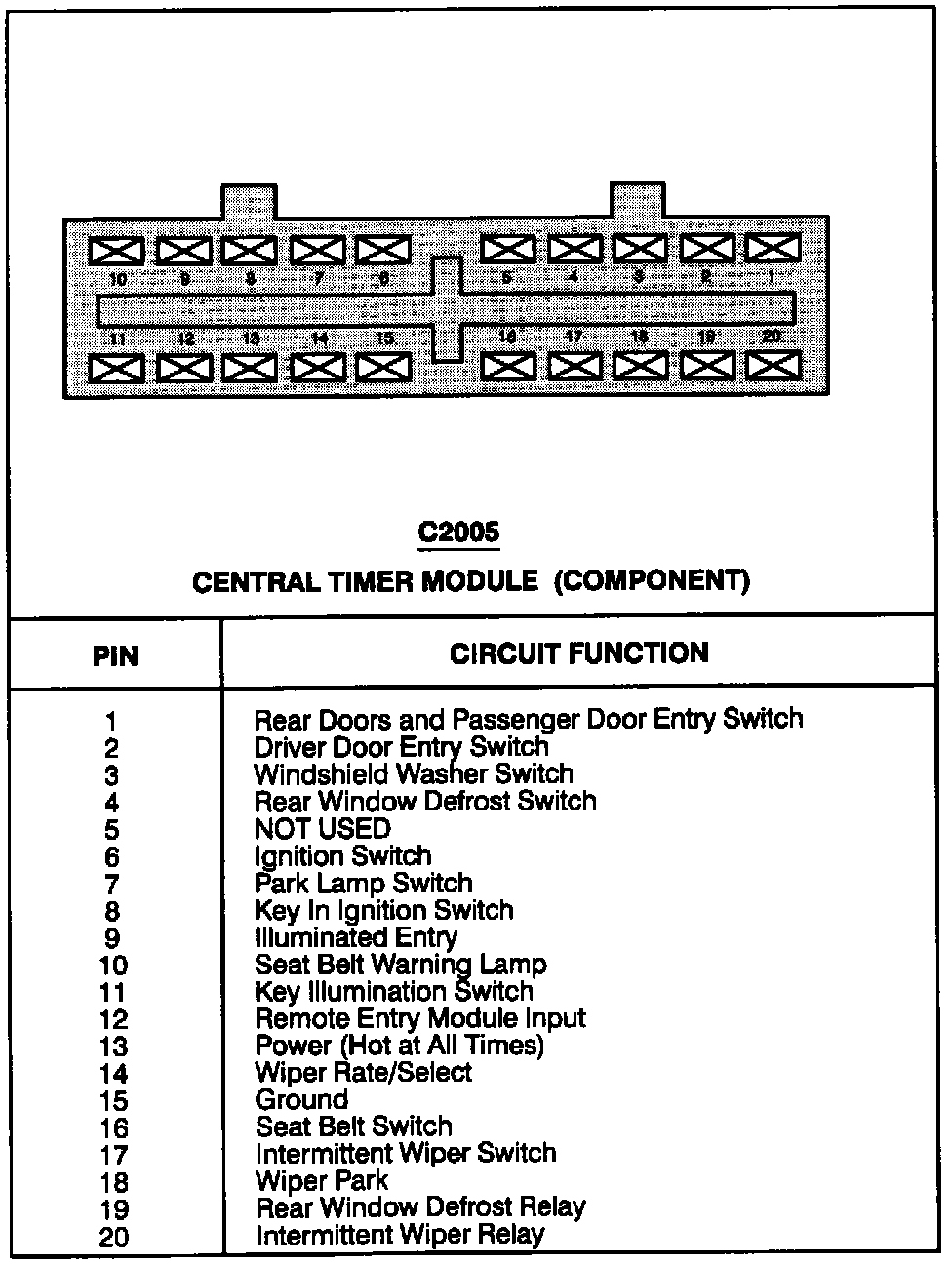
Connector: C2005, Color = 'BK', Terminal= '6'
Central Timer Module Seat Belt Warning Timer