Disassembly
NOTE: Before beginning DISASSEMBLY, perform/inspect the following.
^ The transmission service area should be kept clean, well organized and supplied with clean, lint-free shop cloths.
^ Thorough cleaning of the transmission exterior will reduce the possibility that damaging contaminants might enter the subassemblies during disassembly and assembly.
^ If the transmission is being removed for major overhaul, it is important to completely clean all transmission components, including torque converter, cooler, cooler inlet tubes, main control valve body, all clutches and all coasting booster valve shuttle balls after any transmission servicing that generates contamination. These contaminants are a major cause for recurring transmission troubles and must be removed from the system before the transmission is returned to service. The cleaning of debris from the direct clutch check ball is often omitted. This omission can lead to a repeat servicing of the transmission.
^ Debris that collects and builds up in the corners of the stamped clutches must be removed.
^ The pan magnet should be removed from transmission pan and wiped clean along with the transmission pan.
^ Whenever a seal is removed from a piston, shaft or servo, note the type of seal and when applicable, the direction of the sealing lip.
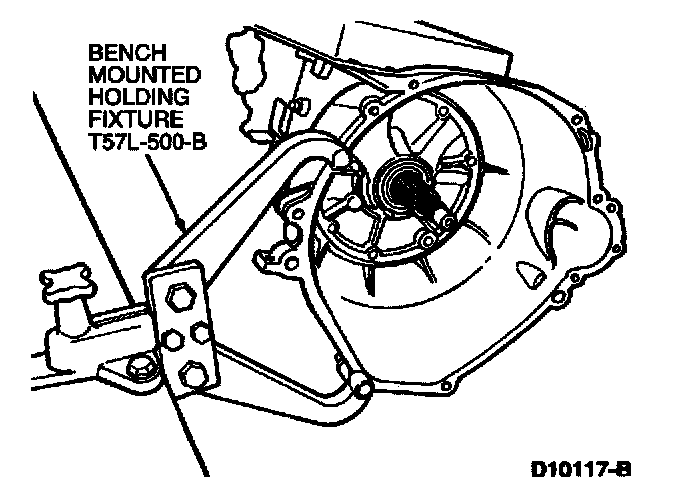
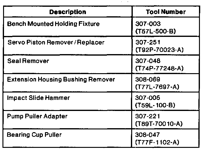
1. Mount transmission in Bench Mounted Holding Fixture 307-003 (T57L-500-B).
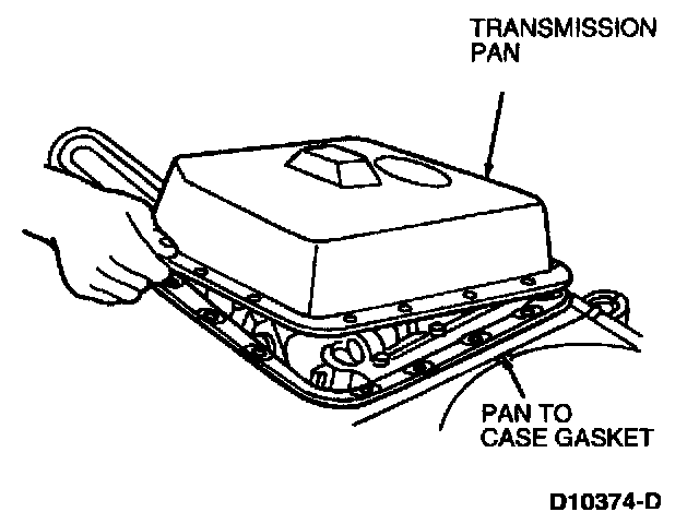
2. Remove 14 pan retaining bolts, transmission pan and pan-to-case gasket.
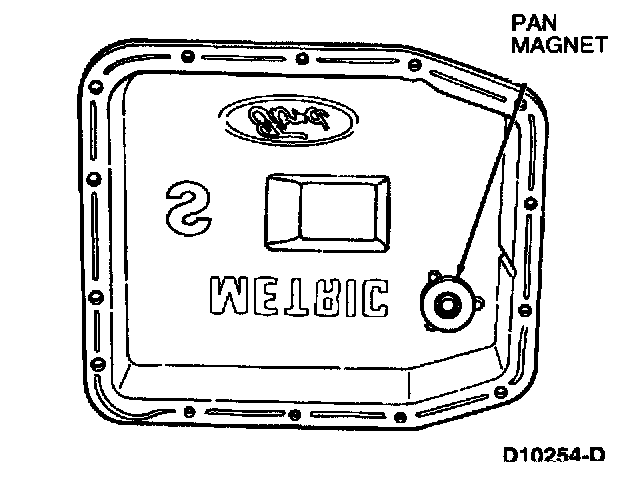
3. Remove pan magnet. Clean transmission pan and pan magnet.
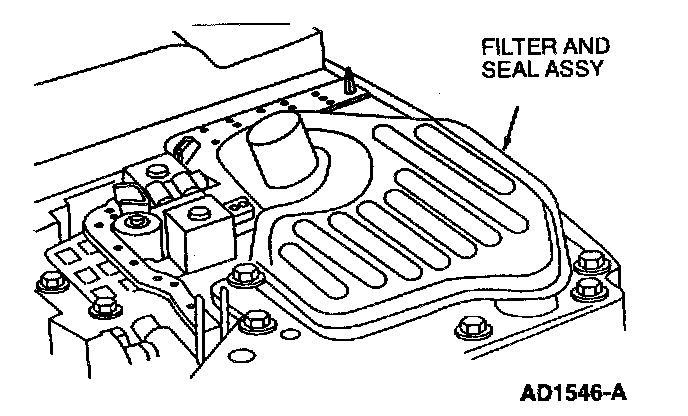
4. CAUTION: If installing a new filter, and grommet remains in the main control bore, carefully use a small screwdriver to remove the grommet. Use care not to damage the main control bore.
NOTE: If transmission is being serviced for a contamination-related failure, use a new filter and grommet. The filter may be reused if no excessive contamination is present.
Using both hands, remove filter by pulling upward.
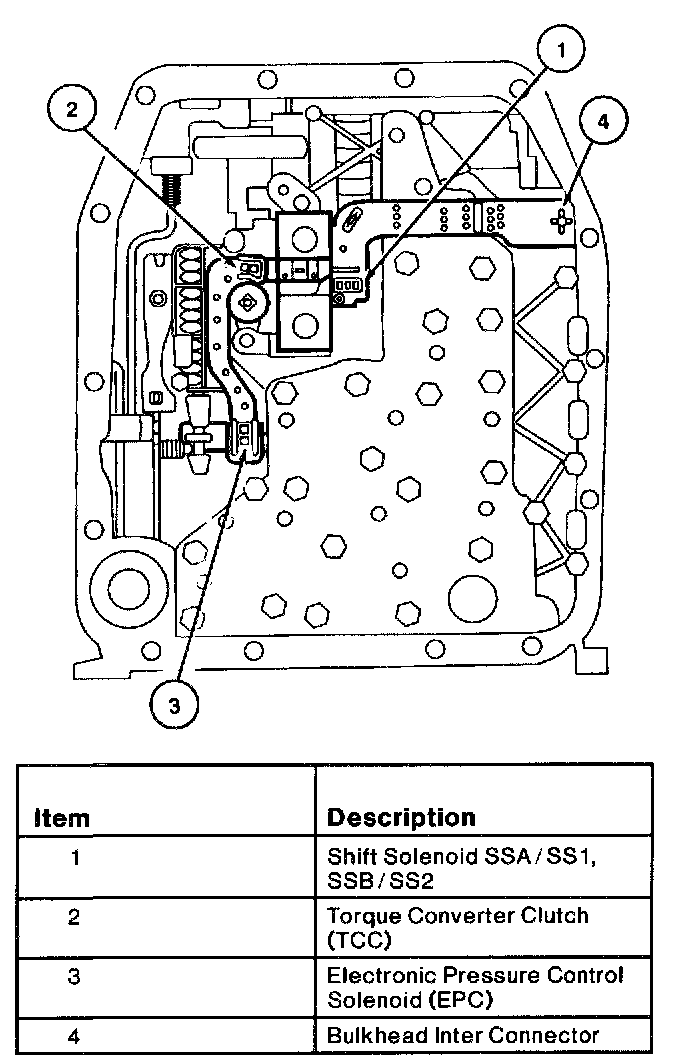
5. CAUTION: Do not pull on the plastic lead frame. This may cause damage to the connector ends. Carefully pry up on locking tabs to disconnect the sensors. Disconnect the molded lead frame from the sensors.
Disconnect the molded lead frame from the sensors.
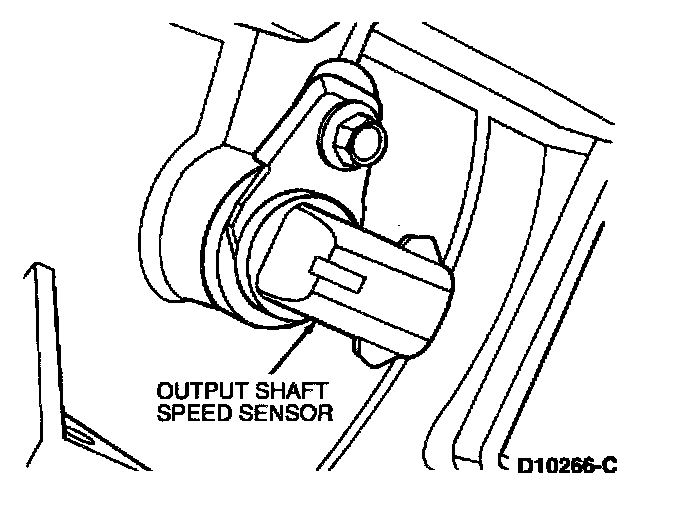
6. NOTE: Removal of the OSS at this time will prevent sensor damage when removing the output shaft.
Remove bolt retaining Output Shaft Speed Sensor (OSS) to case and remove OSS.
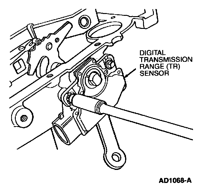
7. Remove two bolts retaining digital Transmission Range (TR) sensor to case. Remove digital Transmission Range (TR) sensor from manual control lever.
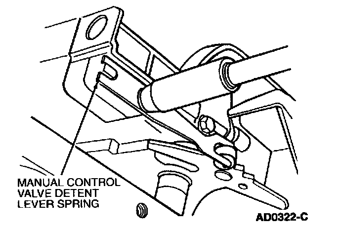
8. Remove one bolt retaining manual control valve detent lever spring to the main control valve body.
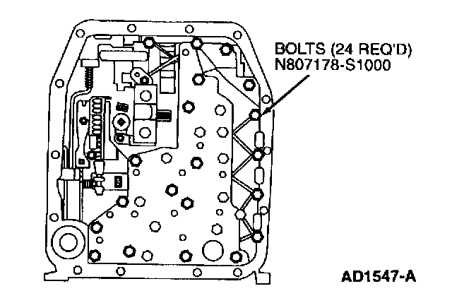
9. Remove remaining 24 valve body-to-case retaining bolts, the main control valve body and the valve-to-body gasket.
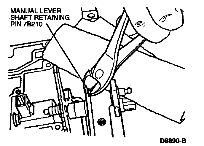
10. NOTE: Use a shop cloth to protect pan-to-case surface.
Remove manual lever shaft retaining pin.
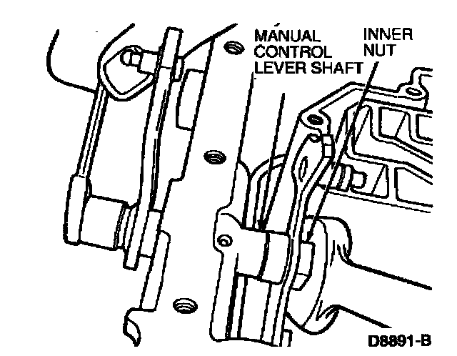
11. Using a 13/16-inch open-end wrench on the inner nut and a 12 mm wrench on the manual control lever shaft flats, loosen the inner nut.
Slide manual control lever partially out of the case to complete removal of the inner nut from manual control lever.
12. NOTE: Do not damage bore with the prying tool.
Using a screwdriver on the manual control lever seal lower edge, carefully pry manual control lever seal out of case bore.
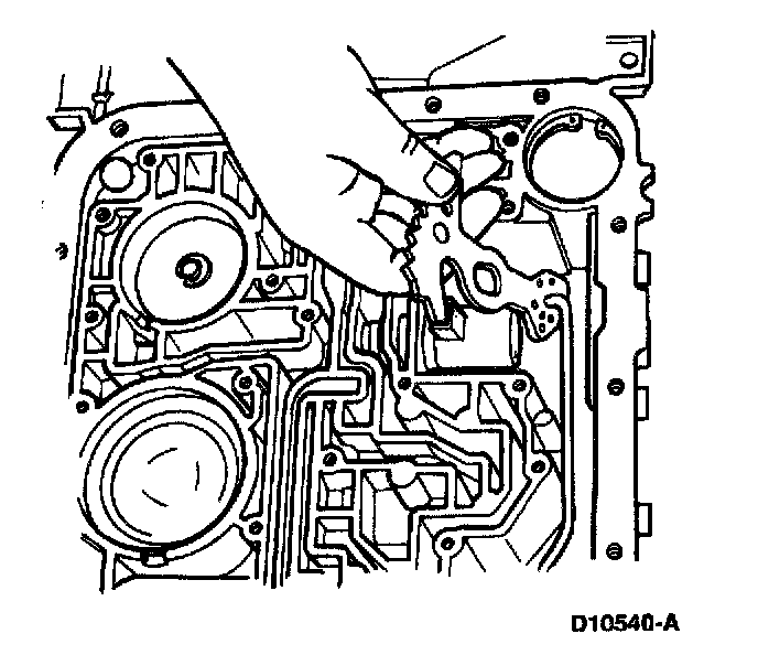
13. Lift manual valve detent lever and parking lever actuating rod out of the case.
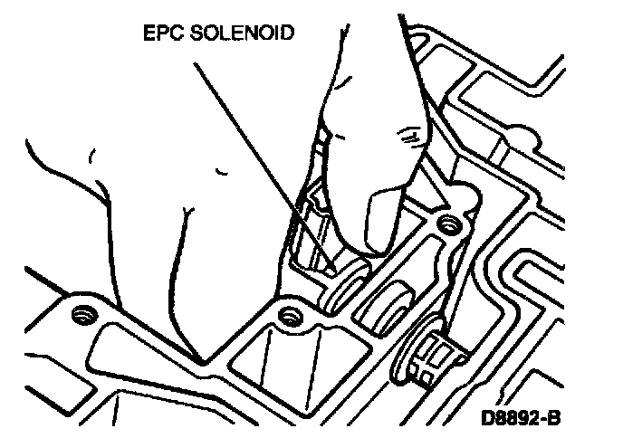
14. Remove Electronic Pressure Control (EPC) solenoid by sliding it out of the case bore.
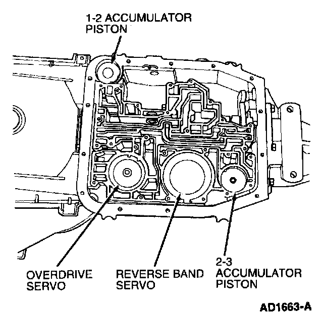
15. This illustration shows the position of the overdrive servo, the reverse band servo, 2-3 accumulator piston and the 1-2 accumulator piston.
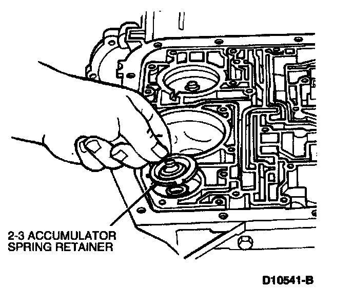
16. Remove the 2-3 accumulator spring retainer.
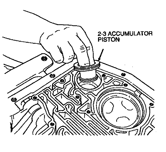
17. Remove 2-3 accumulator piston.
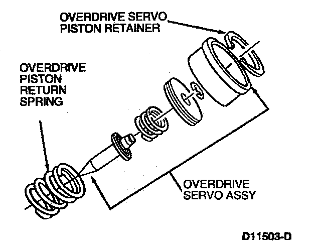
18. NOTE: If tool is not available, extreme care must be taken. Spring pressure will force overdrive servo piston assembly out of case. Case bore damage may result from trying to pry on overdrive servo piston retainer.
Use Servo Piston Remover/Replacer 307-251 (T92P-70023-A) to compress the overdrive servo piston return spring. Use snap-ring pliers to remove retainer ring.
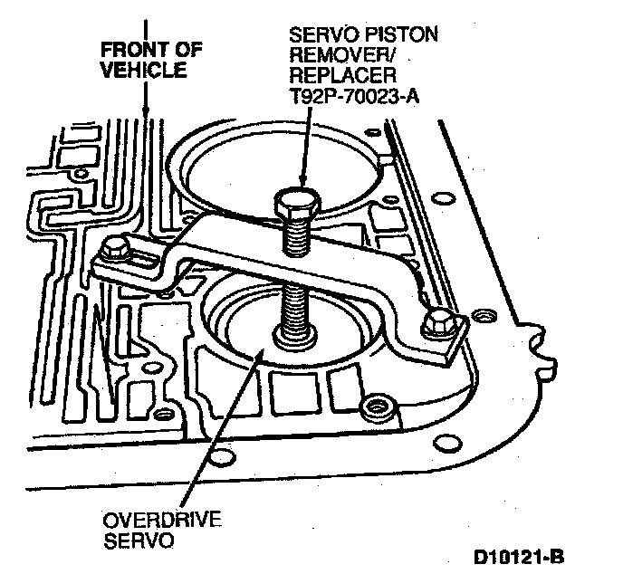
19. Remove piston assembly. Remove overdrive servo piston return spring.
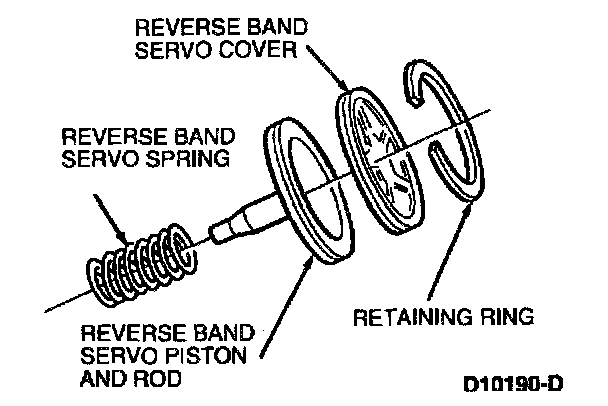
20. Use Servo Piston Remover/Replacer 307-251 (T92P-70023-A) to contact the reverse band servo cover and compress return spring and remove servo cover retaining ring.
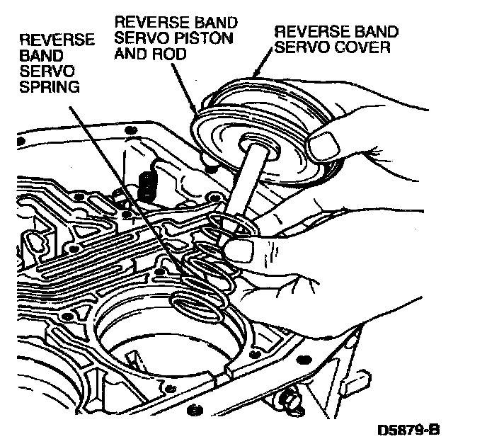
21. NOTE: The length of the rod attached to the piston is graded in three different lengths. Therefore, they should not be installed in any transmission other than the transmission from which they were removed.
Remove reverse band servo cover, reverse band servo piston and rod and reverse band servo spring.
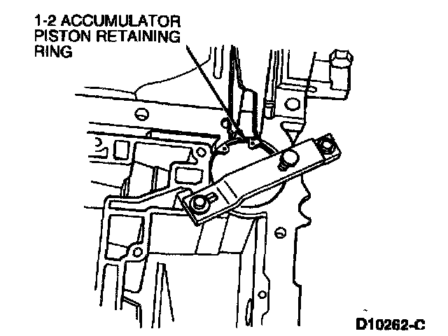
22. Apply downward pressure on 1-2 accumulator cover using Servo Piston Remover/Replacer 307-251 (T92P-70023-A). Using snap-ring pliers, remove 1-2 accumulator piston retaining ring.
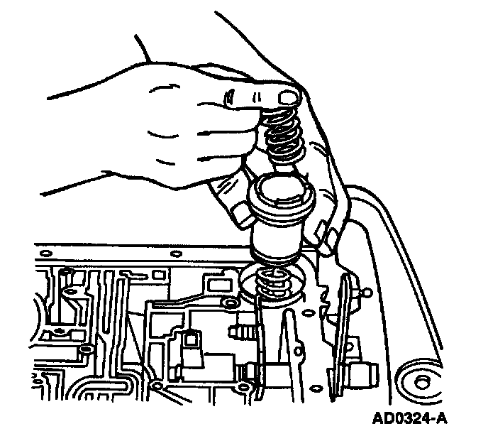
23. Carefully note the location of the 1-2 accumulator springs and assemble in the same positions. Some models may use two 1-2 accumulator springs. The accumulator piston may also vary with applications. Remove accumulator piston and 1-2 accumulator spring.
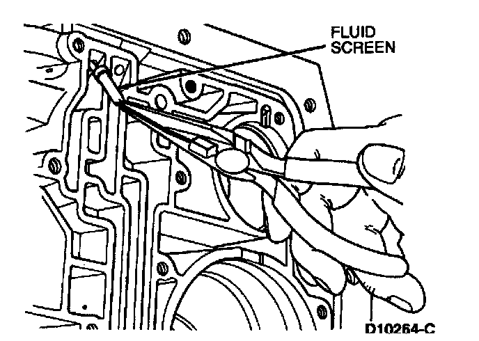
24. Remove fluid screen from case.
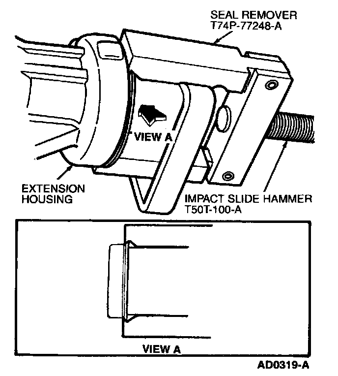
25. Remove extension housing seal using Seal Remover 307-048 (T74P-77248-A). Make sure seal remover lips are firmly seated under the flange on the extension housing seal.
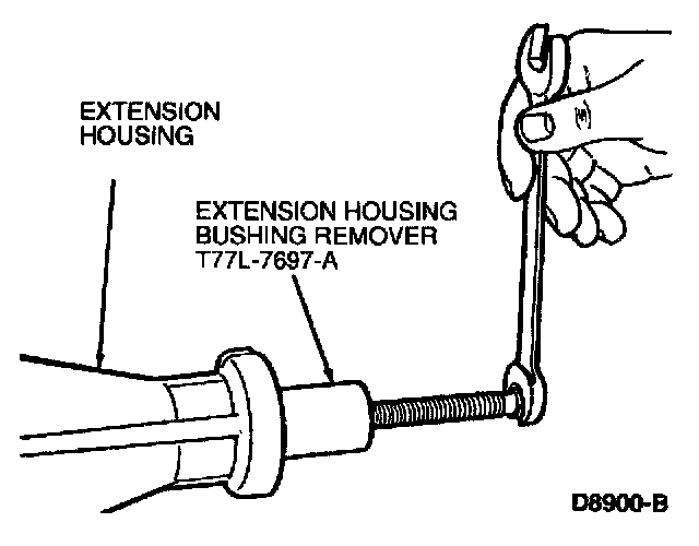
26. Inspect extension housing bushing. If required, remove the extension housing bushing using Extension Housing Bushing Remover 308-069 (T77L-7697-A).
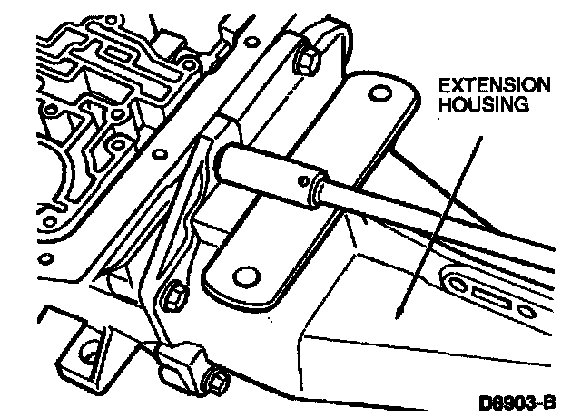
27. NOTE: The extension housing bolts have been coated with a sealant. More break torque may be required to remove these bolts.
Remove six extension housing bolts. Remove and discard extension housing gasket.
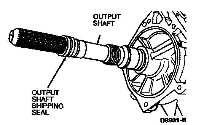
28. The output shaft may have shipping seal still attached. Remove and discard. This seal is not required for assembly.
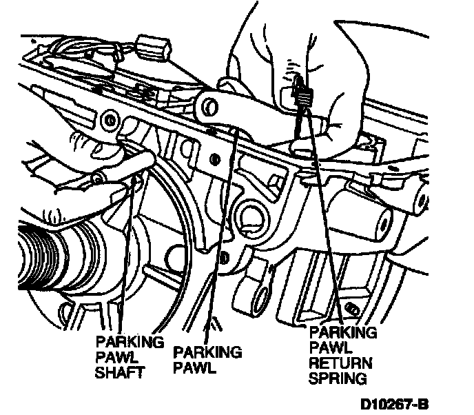
29. Slide parking pawl shaft out of the case and remove parking pawl and parking pawl return spring.
30. Place transmission in the vertical position with output shaft toward floor.
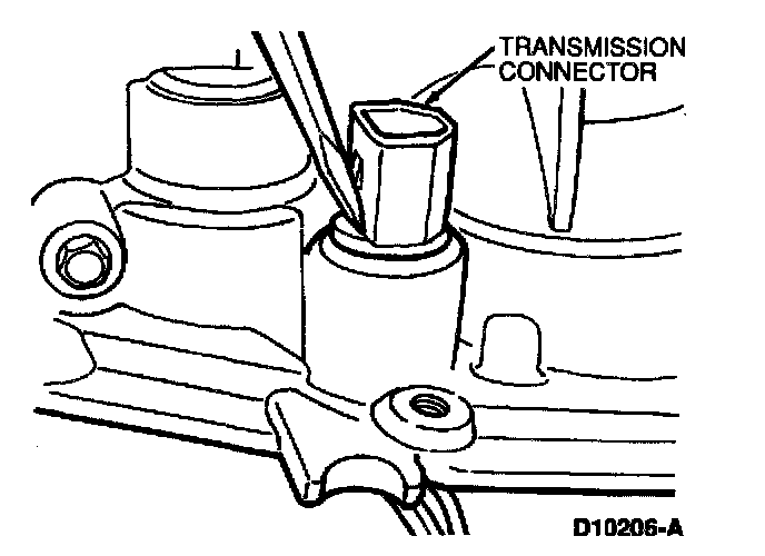
31. CAUTION: Extreme care must be taken during transmission connector removal. Do not pull on the wires, or use a hammer on the connector body. This will damage wires or connector and could result in a transmission concern.
Remove transmission connector from case. Place a screwdriver on the flat portion of the connector and drive the connector out through the bottom of the case.
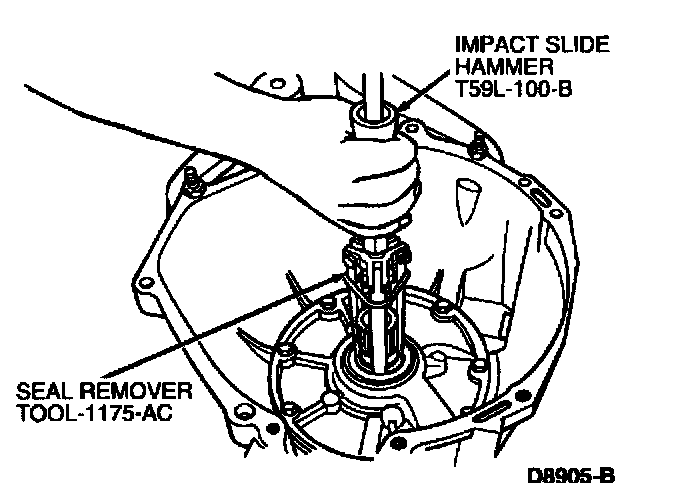
32. Remove front pump seal using Seal Remover 307-001 (TOOL-1175-AC) or equivalent and Impact Slide Hammer 307-005 (T59L-100-13).
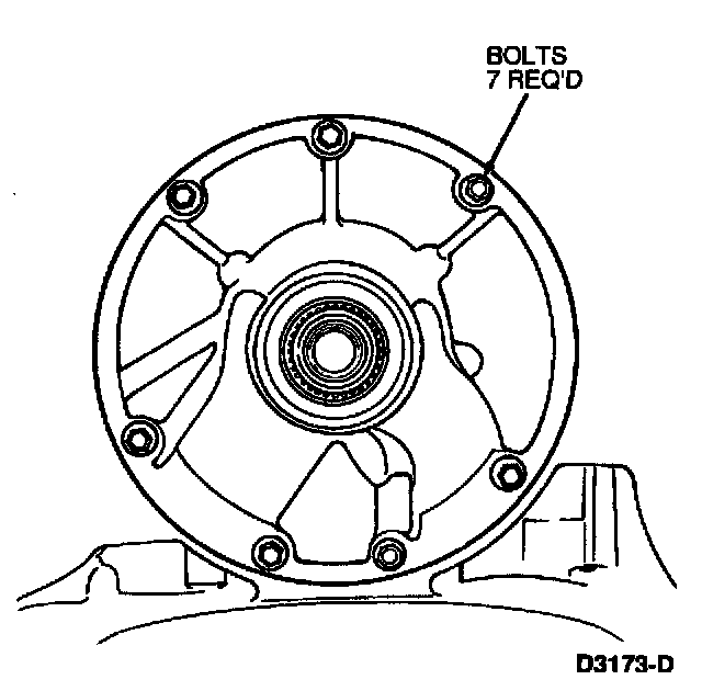
33. NOTE: All bolts have been coated with a sealant. More break torque might be required to remove bolts.
Remove seven pump body retaining bolts.
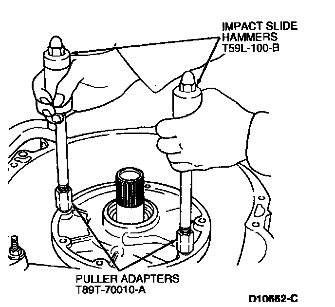
34. Remove front pump and support assembly using two Impact Slide Hammers 307-005 (T59L-100-13) and Pump Puller Adapters 307-221 (T89T-7001O-A).
35. Remove and discard pump gasket.
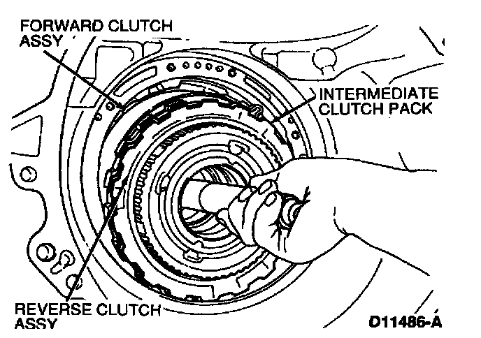
36. CAUTION: Remove the assembly carefully to prevent damage to the overdrive band friction material by the reverse clutch drive lugs.
Grasp the forward clutch cylinder and shaft firmly and pull the following components out of the case as an assembly:
^ intermediate clutch pack
^ intermediate one-way clutch
^ reverse clutch assembly
^ forward clutch assembly
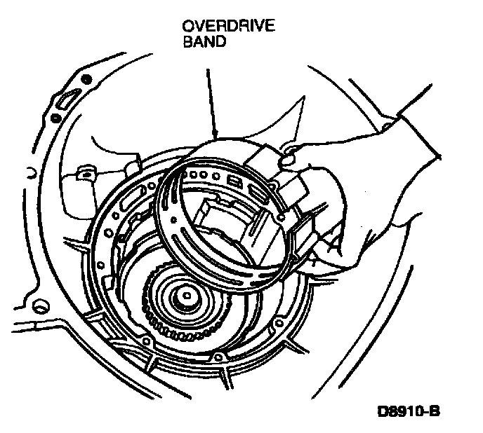
37. NOTE: Band may be removed with assembly.
Disengage overdrive band from overdrive band anchor pin and remove.
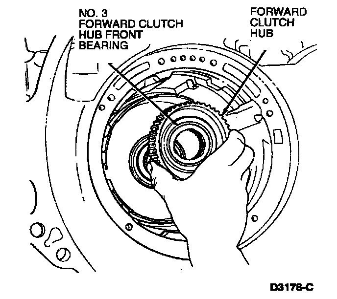
38. Remove forward clutch hub and the No. 3 forward clutch hub front bearing.
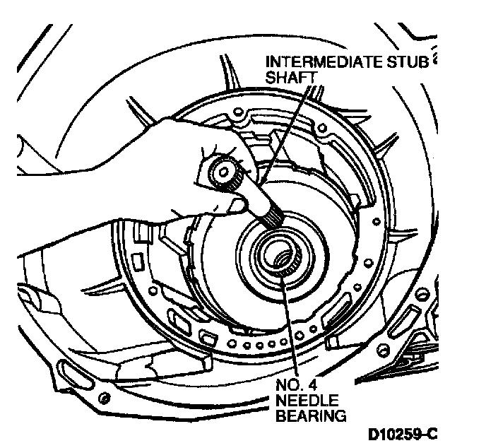
39. Remove intermediate stub shaft.
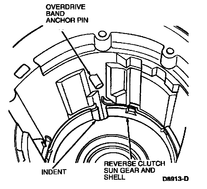
40. Rotate reverse clutch gear and shell to align indent with overdrive band anchor pin.
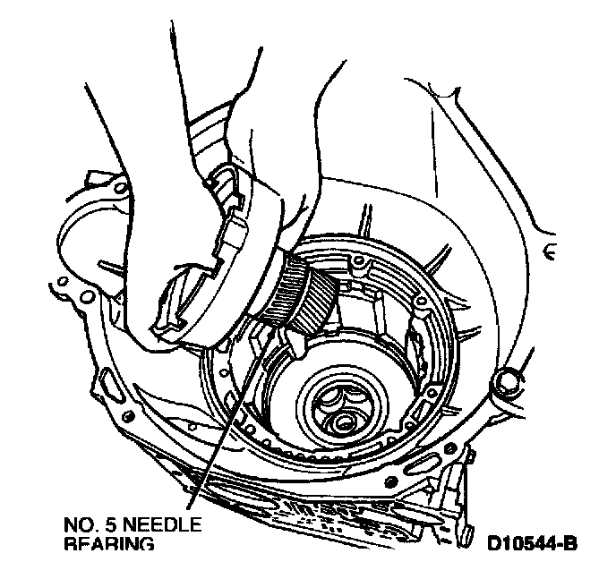
41. Remove forward clutch sun gear, No. 5 needle bearing, reverse clutch gear and shell and the No. 4 needle bearing as an assembly.
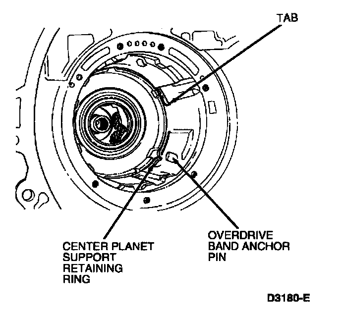
42. Remove center planet support retaining ring. Note position of retaining ring tabs for assembly.
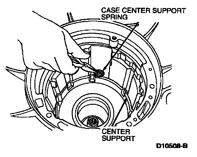
43. Using needle-nose pliers, remove case to center support spring out from between the center support and the case. Note location for assembly.
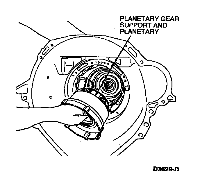
44. Remove planetary gear support and planetary as an assembly.
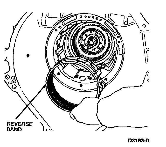
45. Remove reverse band.
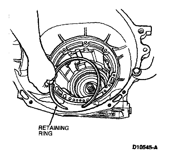
46. Remove retaining ring.
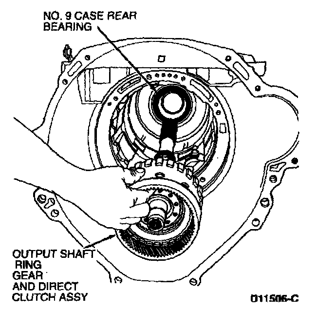
47. Remove output shaft, ring gear and direct clutch assembly as a unit, from the front of the case.
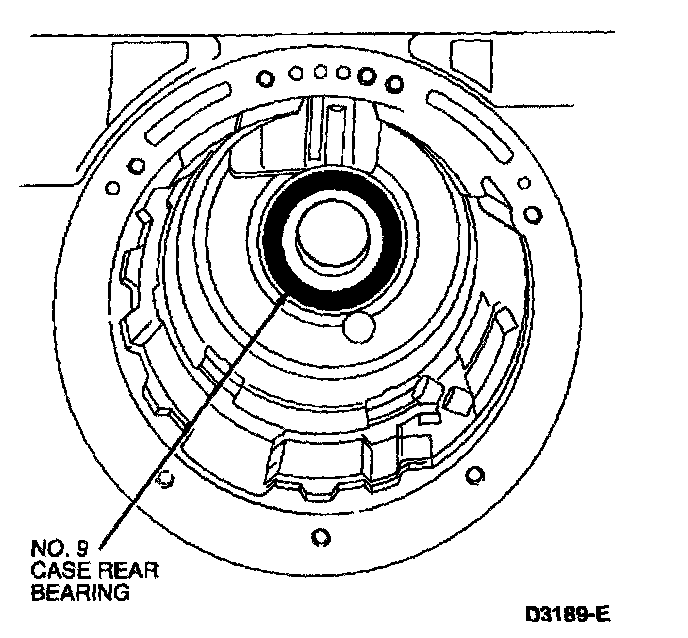
48. Remove No. 9 case rear bearing from rear of the case.
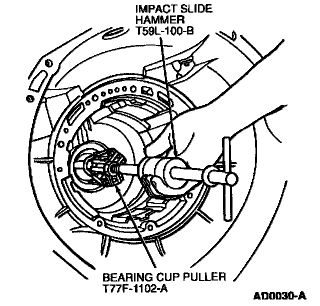
49. Inspect output shaft bushing. If removal is required, use Bearing Cup Puller 308-047 (T77F-1102-A) and Impact Slide Hammer 307-005 (T59L-100-B).