Assembly
1. If removed, install oil gallery and cooling jacket plugs. Tighten plugs to 20 Nm (14 ft. lbs.). Before installation, coat plug threads with Pipe Sealant with Teflon.NOTE:
- During assembly of the engine, Gasket Maker will be applied to many areas before installation. When the sealant is applied, the component should be installed within 15 minutes. After this time the sealant begins to set-up and its sealing effectiveness can be reduced.
- Lightly oil all retaining bolt and stud bolt threads with clean engine oil meeting Ford specification before installation except those specifying special sealant.
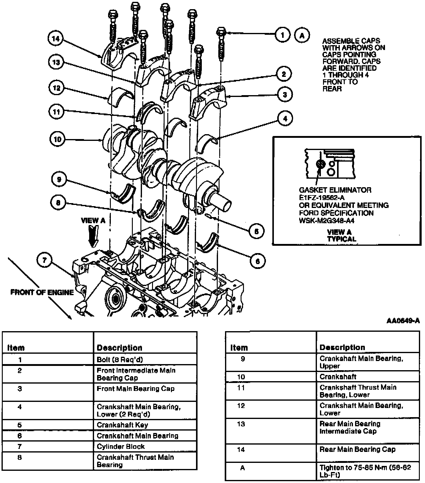
2. Install crankshaft as follows:
a. Install crankshaft main bearings in the appropriate cylinder block saddle. Note that third bearing from front is the crankshaft thrust main bearing.
b. Lubricate crankshaft main bearings with Engine Assembly Lubricant. Carefully lower the crankshaft into place.
CAUTION: Use care to prevent damage to bearing surfaces or engine damage may occur.
c. Apply a 6 mm (0.25-inch) dot of Gasket Eliminator between rear main bearing cap and cylinder block.
NOTE: Prior to applying sealer, clean sealing surfaces with Metal Surface Cleaner to remove all residue that may interfere with the sealer's ability to adhere.
d. Install lower crankshaft main bearings in the main caps. Note that caps are numbered with arrow heads. No. 1 is located at front of engine with arrow head facing front of engine. No. 2 is main bearing cap and has two arrow heads pointing to front of engine and so on.
e. Apply clean engine oil to main bearing caps. Install bolts finger-tight.
NOTE: Crankshaft main bearing caps are precision fit to surrounding metal parts. A slight tap with a plastic mallet will help to locate cap. Use care to prevent damage.
f. Before tightening main bearing cap retaining bolts/stud bolts, wedge a large pry bar between cylinder block web and crankshaft cheek located in front of the No. 3 crankshaft main bearing. Do not jam the pry bar into place. Apply sufficient force only to push crankshaft forward while the main bearing cap bolts are tightened.
g. Tighten main bearing cap retaining bolts/stud bolts to 75-85 Nm (56-62 ft. lbs.) and remove pry bar.
h. Check crankshaft end play.
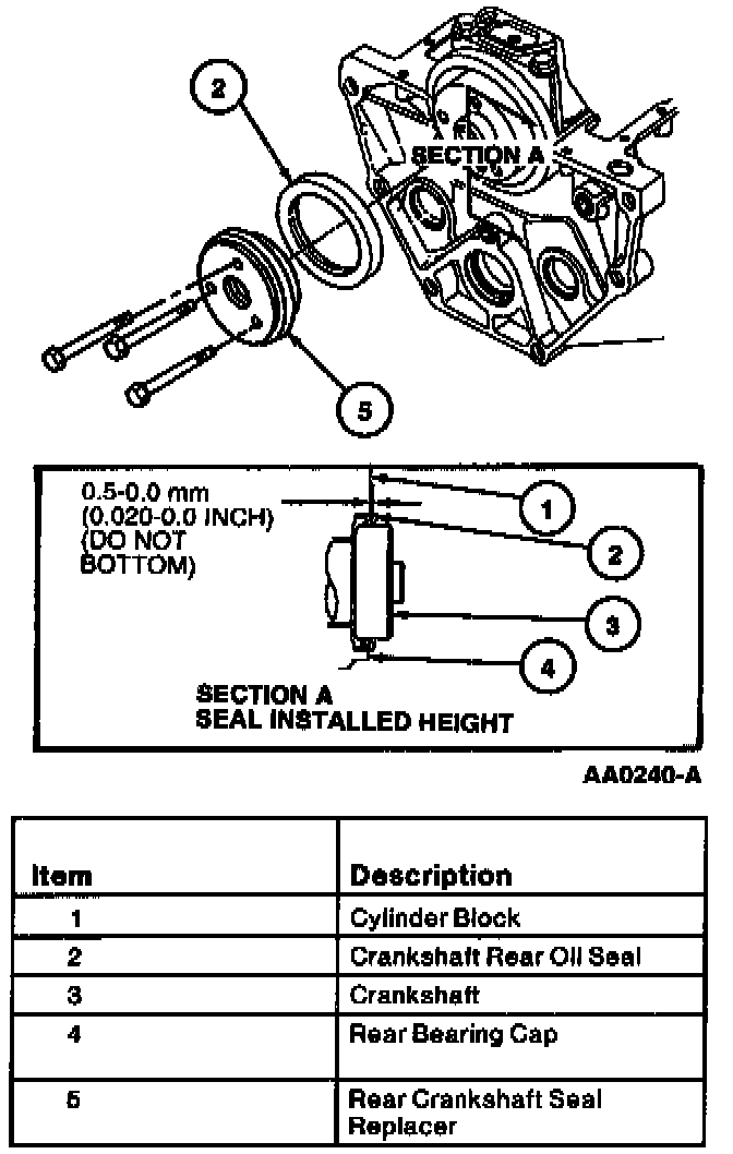
3. Install crankshaft rear oil seal.
4. Install piston rings on pistons using a ring expander. Make sure piston ring lands are completely clean of carbon deposits before installing rings. Check piston ring end gap in each cylinder prior to piston installation.
Part 1 Of 2:
Part 2 Of 2:
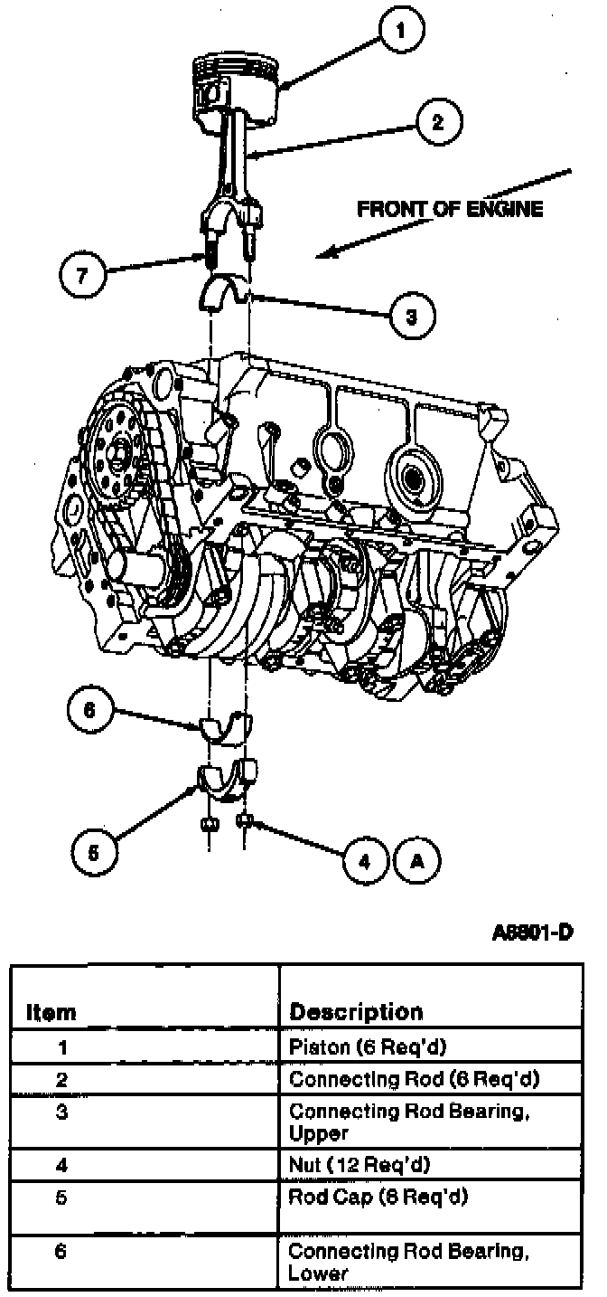
5. Install the piston as follows:
a. Install connecting rod bearings in the connecting rods and the connecting rod caps. Make sure bearing locating tang is properly located and connecting rod bearing is completely seated.
b. Lubricate piston rings, cylinder walls, and bearing surfaces with Engine Assembly Lubricant.
c. Arrange piston ring gaps alternately around the pistons. Do not allow gaps to align.
d. Install a 50 mm (2 inch) piece of 3/8 inch fuel line (or straight ignition wire spark plug boot) on both connecting rod bolts prior to installation to prevent damage to crankshaft rod journals.
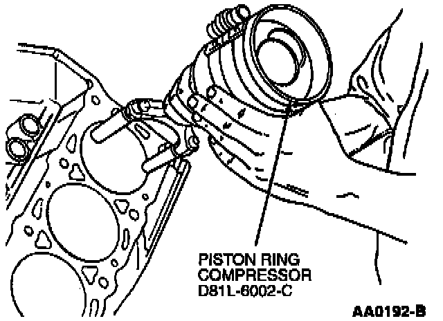
e. Install pistons using Piston Ring Compressor. The notch in the piston dome and button on connecting rods must face the front of the engine.
f. Rotate crankshaft journal to bottom of its stroke for each piston installation. Using a wooden hammer handle, tap piston into cylinder bore. At the same time, guide connecting rod end into position onto crankshaft journal. Seat connecting rod bearing fully against journal. Remove rubber protection from connecting rod bolts. Aligning both bearing locating tangs on the same side, install connecting rod cap and retaining nuts.
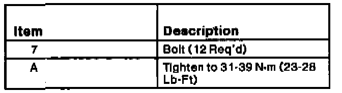
- Alternate evenly between both retaining nuts, tighten to 31-39 Nm (23-28 ft. lbs.).
6. Check connecting rod side clearance.
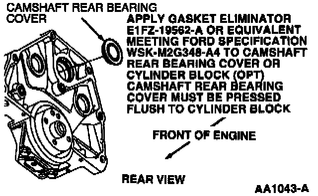
7. Install camshaft rear bearing cover. Coat the sealing edge of the camshaft rear bearing cover with Perfect Seal Sealing Compound before installation. Using a suitable driver, install camshaft rear bearing cover square into bore.
8. If necessary, replace camshaft bearings.
9. Lubricate camshaft lobes, distributor drive gear and bearing surfaces with Engine Assembly Lubricant. Carefully slide camshaft through camshaft bearings into cylinder block. Remember to keep camshaft perfectly in line with front camshaft bearing.

10. Install camshaft thrust plate. Tighten retaining bolts to 10 Nm (88 inch lbs.).
11. Check camshaft end play.
Fig. 8 Timing Chain Alignment:

12. Install timing chain, camshaft sprocket and crankshaft sprocket as an assembly. Lubricate timing chain with Engine Assembly Lubricant.
Rotate crankshaft and camshaft to align sprocket timing marks as shown.
13. Install camshaft sprocket retaining bolt and washer and tighten to 60-70 Nm (37-51 ft. lbs.). Check the drilled oil passages of the bolt to ensure they are not plugged. Clean as required. Do not replace with a standard bolt.
14. Install the water pump/engine front cover as an assembly and a new engine front cover gasket. Tighten water pump retaining bolts.

15. Install oil pump and oil pump intermediate shaft. If installing new oil pump, insert oil pump intermediate shaft into oil pump hex drive hole until oil pump intermediate shaft retaining ring clicks into place. Tighten retaining bolts to 40-55 Nm (30-40 ft. lbs.).

Part 2 Of 2:
16. Locate oil pan gasket to oil pan and secure with Gasket and Trim Adhesive. Apply a 5 mm (0.187 inch) bead of Silicone Gasket and Sealant to the engine front cover-to-cylinder block junction, and to the rear main bearing cap-to-cylinder block junction.
NOTE: Prior to applying sealer, clean sealing surfaces with Metal Surface Cleaner to remove all residues that may interfere with the sealer's ability to adhere.
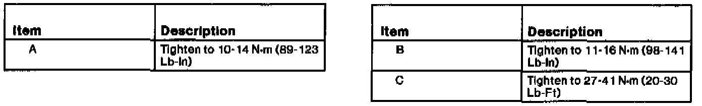
17. Install oil pan and tighten retaining bolts to 10-14 Nm (89-123 inch lbs.). Tighten the four corner fasteners first, then tighten remaining twelve. Back off all retaining bolts and then re-tighten to the original value.
18. Lubricate oil bypass filter gasket with Engine Assembly Lubricant and install oil bypass filter.
19. Lubricate valve tappets with Engine Assembly Lubricant and install into their original positions relative to camshaft lobe and push rod.
20. Install new head gaskets onto cylinder block using the cylinder head to block dowel to align the head gasket.
NOTE: Make sure the "UP" designation is facing the cylinder head.

21. Install cylinder heads. Tighten retaining bolts in four steps in the sequence shown in the following illustration:
- tighten to 80 Nm (59 ft. lbs.)
- loosen 360 degrees
- tighten to 50 Nm (36 ft. lbs.)
- tighten to 92 Nm (67 ft. lbs.)
22. Apply Silicone Rubber to intersection of cylinder block end rails and cylinder heads (four places).
NOTE: Prior to applying sealer, clean sealing surfaces with Metal Surface Cleaner to remove all residues that may interfere with the sealer's ability to adhere.
23. Install front and rear intake manifold end seals.
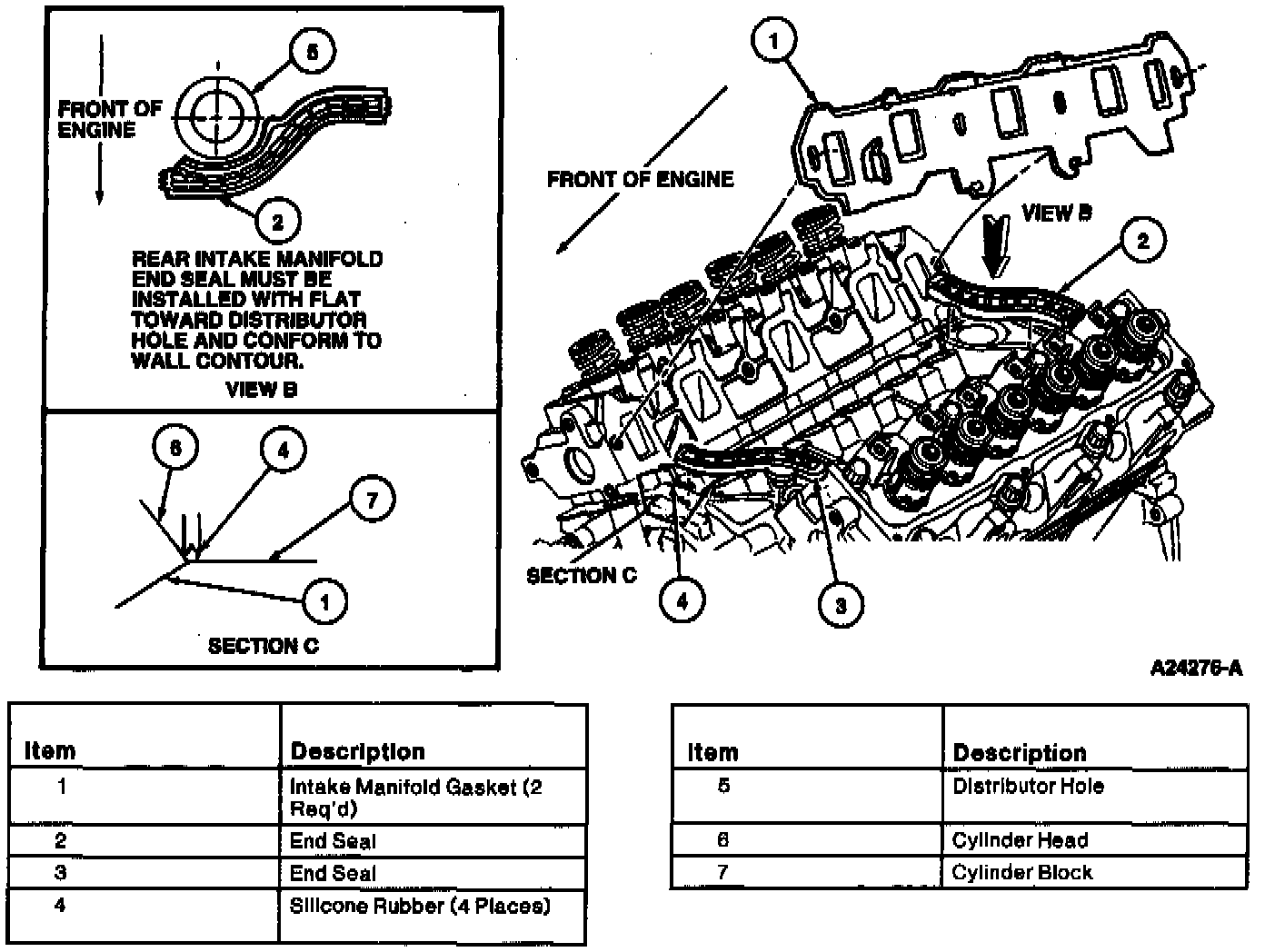
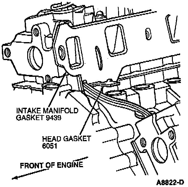
24. Position intake manifold gaskets in place.
25. Carefully lower intake manifold into position to prevent smearing the silicone sealer and causing leak paths.
NOTE: Intake manifold gaskets are marked "TO INTAKE MANIFOLD" which faces intake manifold sealing surface. Insert locking tabs over head gasket locating tabs as shown.

26. Install retaining bolts and tighten in numerical sequence as shown to the following specifications in two steps:
- 20-30 Nm (15-22 ft. lbs.)
- 26-32 Nm (20-23 ft. lbs.)
NOTE: Retaining bolts require a Torx head socket.
27. Lubricate push rods and rocker arms with Engine Assembly Lubricant.
CAUTION: Rocker arm seats must be fully seated in cylinder head, and push rods must be seated In rocker arm sockets prior to final tightening.
28. Install push rods in their original positions.
29. Rotate rocker arms onto push rods making sure push rod is seated properly on valve tappet and in rocker arm. Tighten retaining bolt to 7-15 Nm (62-132 inch lbs.) to seat rocker arm seats into cylinder head.
30. Rotate crankshaft to position valve tappet on the heel of the camshaft lobe (base circle - O lift).
- Tighten retaining bolts of specified rocker arms to 7-15 Nm (62-132 inch lbs.).
- Final-tighten all rocker arm seat bolts (camshaft may be in any position) to 26-38 Nm (20-28 ft. lbs.).

31. Install water hose connection and water hose connection gasket as illustrated if removed. Tighten retaining bolts to 10-14 Nm (89-123 inch lbs.).
32. Install fuel injection supply manifold and fuel injectors if removed.
Install fuel injection supply manifold retaining bolts and tighten to 8-12 Nm (71-106 inch lbs.).
NOTE: Apply Engine Assembly Lubricant to fuel injector bores in intake manifold and fuel injection supply manifold prior to fuel injector installation.
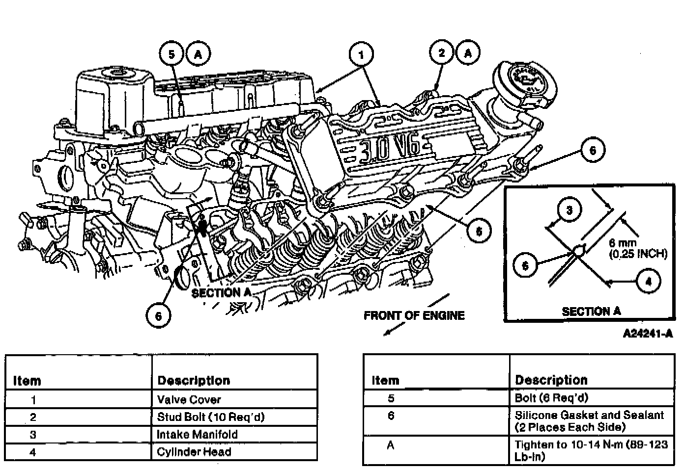
33. Install valve covers. Install retaining bolts and stud bolts. Tighten to 10-14 Nm (89-123 inch lbs.).
34. Install oil filler cap.
35. Install engine control sensor wiring to the appropriate locations. Locate and install harness retainers to the valve cover retaining stud bolts.
36. Install throttle body and new intake manifold upper gasket.
37. Coat entire camshaft position sensor housing gear with Engine Assembly Lubricant and install camshaft position sensor housing and camshaft position sensor.
CAUTION: If a new camshaft and/or camshaft position sensor housing is installed, ALWAYS add the rest (pint) of the Engine Assembly Lubricant to the engine oil by pouring it through the hole onto the camshaft drive gear. Run engine at idle for five minutes prior to driving vehicle.
38. Install exhaust manifolds. Tighten retaining bolts to 20-30 Nm (15-22 ft. lbs.).
39. NOTE: Apply Perfect Seal Sealing Compound prior to installation.
Install oil level dipstick and oil level indicator tube. Tighten retaining nut to 15-20 Nm (111-114 ft. lbs.).
40. Install spark plugs.
41. Connect ignition wires to spark plugs. Locate with ignition wire separators to appropriate valve cover retaining stud bolts.
42. Install crankshaft damper using Vibration Damper and Seal Replacer. Tighten retaining bolt to 125-165 Nm (93-121 ft. lbs.).
43. Install oil pan. Tighten retaining bolts to 10-14 Nm (89-123 inch lbs.).
NOTE: Apply Silicone Rubber to keyway slot in damper and lubricate outside of damper hub with clean engine oil prior to installation.