Connecting Rod: Service and Repair
REMOVAL1. Drain engine cooling system.
2. Remove upper intake manifold and lower intake manifold.
3. Remove cylinder heads.
4. Remove oil pan.
5. Remove oil pump screen cover and tube.
6. Before removing piston, inspect top of each cylinder bore. If a ridge has formed at the top of the cylinder bore, it must be removed before piston removal. Remove ridge as follows:
a. Turn crankshaft until piston to be removed is at bottom of cylinder bore.
b. Place a clean shop cloth over piston head to collect cuttings.
c. Remove ridge using Cylinder Ridge Reamer. Never cut into ring travel area more than 0.8 mm (0.031 inch) when removing ridge.
7. Turn crankshaft until piston to be removed is at the low point of its travel.
If more than one piston is being removed, identify the pistons, connecting rod bearings and connecting rod caps. Each component should be installed in its original position during assembly.
8. Remove connecting rod cap retaining bolts, connecting rod cap and lower connecting rod bearing.
9. Turn crankshaft until piston to be removed is at the high point of its travel. If more than one piston is being removed, identify the pistons, connecting rods and connecting rod caps for cylinder position.
Remove the connecting rod cap and lower connecting rod bearing. Keep cap and lower connecting rod bearing together. Push the piston, connecting rod and upper connecting rod bearing through the top of the cylinder bore. Use care to prevent damage to the connecting rod bearing and cylinder bore surfaces. Keep upper connecting rod bearing and connecting rod together.
CAUTION: Care should be taken not to damage the fractured rod and cap joint. face surfaces or possible damage to engine may occur.
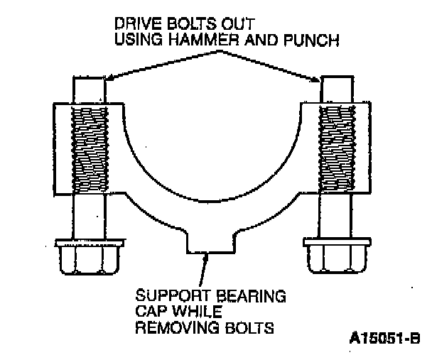
NOTE: Connecting rod bolts are retained in the bolt hole with a light press fit. The connecting rod bolts have been tightened to yield at least twice and must be discarded. Use a hammer and punch to drive connecting rod bolts from connecting rod cap.
10. Using a new connecting rod bolt, attach cap and lower connecting rod bearing to connecting rod and upper connecting rod bearing to prevent mixing parts and damaging the fractured joint face surfaces.
11. If piston is to be disassembled, refer to Piston, Engine/Service and Repair/Disassembly and Assembly. Disassembly And Assembly
12. Inspect cylinder bore. If new piston rings are to be installed on the piston a visible cross-hatch pattern should be obvious on the cylinder bore wall.
13. After honing, thoroughly clean cylinder bore using a detergent and water solution.
NOTE: If honing is required, remove glaze from cylinder wall using spring-loaded hone. Follow manufacturer's instructions when using this type of equipment.
INSTALLATION
1. Lubricate cylinder wall and piston with Engine Assembly Lubricant.
NOTE: Lightly oil all bolt threads before installation except those specifying special sealant with clean engine oil.
2. Install connecting rod guide on connecting rod bolt holes.
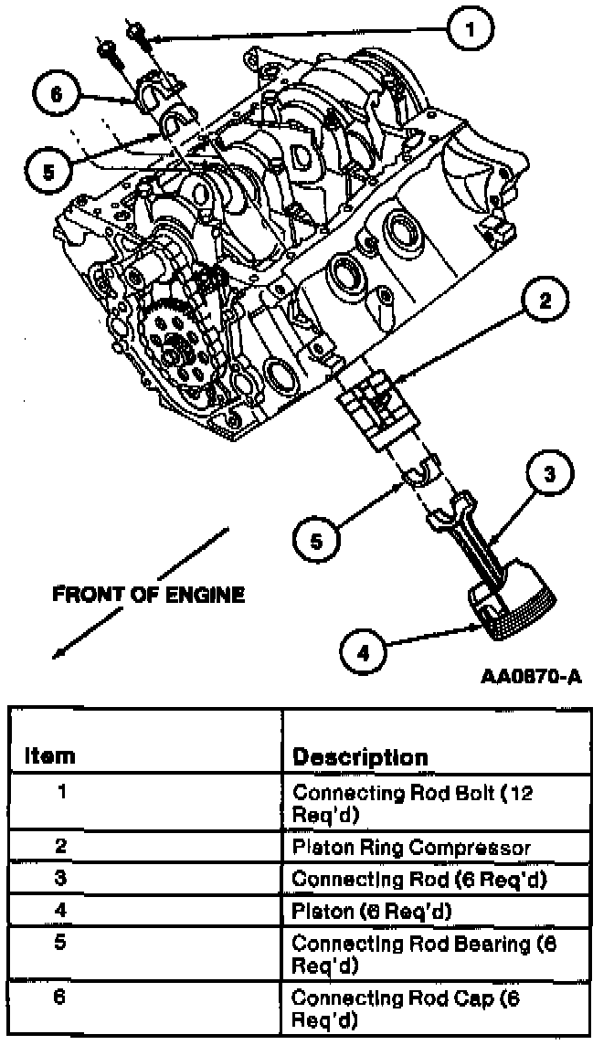
3. Install piston, connecting rod and upper connecting rod bearing using Piston Ring Compressor.
CAUTION: As piston is tapped into bore with a hammer handle, guide connecting rod onto crankshaft journal to avoid damage to bearing surfaces.
NOTE:
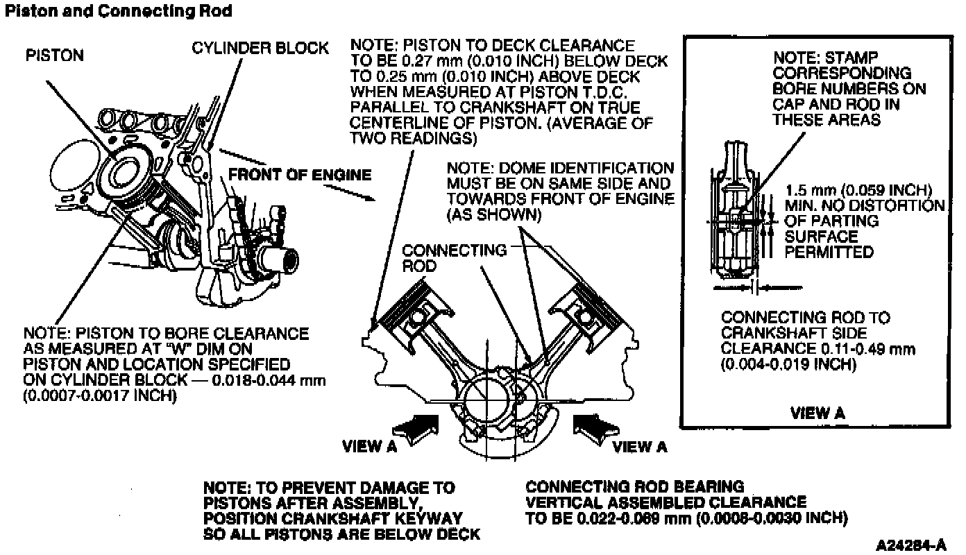
- Install pistons in the same cylinders from which they were removed or to which they were fitted. The connecting rod and caps are numbered from 1 to 3 in the RH bank and from 4 to 6 in the LH bank, beginning at the front of the engine. Numbers on connecting rod and connecting rod cap must be on the same side when installed in cylinder bore. If a connecting rod is transposed from one cylinder block or cylinder to another, new connecting rod bearings should be fitted and connecting rod should be numbered to correspond with new cylinder number.
- Make sure stamped arrow in piston dome faces front of engine.
4. Check connecting rod bearing clearance.
5. Lubricate bearing surfaces with Engine Assembly Lubricant.
6. Make sure connecting rod is seated on crankshaft journal. Install connecting rod cap.
7. Alternately tighten new connecting rod cap bolts in several passes to obtain 40-45 Nm (29-34 ft. lbs.) and rotate connecting rod bolts an additional 90-120 degrees. After installation, rotate crankshaft to ensure smooth operation.
NOTE: Due to the use of a cracked connecting rod joint face surface, the connecting rod cap must be properly aligned to the connecting rod. The connecting rod and connecting rod cap bearing tangs should be located on the same side of the connecting rod.
8. If necessary, check connecting rod side clearance.
9. Install oil pump screen cover and tube with a new oil pump inlet tube gasket. Tighten oil pump screen cover and tube retaining bolts to 20-30 Nm (15-22 ft. lbs.).
10. Tighten oil pump screen cover and tube support bracket retaining nut to 40-56 Nm (30-40 ft. lbs.).
11. Install oil pan.
12. Check piston deck clearance and bore clearance as described in Piston and Connecting Rod illustration.
13. Install cylinder heads.
14. Install lower intake manifold and upper intake manifold.
15. Fill crankcase with the correct viscosity and amount of engine oil.
16. Fill and bleed engine cooling system.
17. Start engine and check for oil and coolant leaks.