Lower
REMOVAL1. Drain engine cooling system.
2. Remove upper intake manifold.
3. Disconnect upper radiator hose from water hose connection.
4. Disconnect water bypass hose from heater water outlet tube.
5. Remove water bypass hose from lower intake manifold.
6. Release pressure from fuel system.
7. Disconnect engine control sensor wiring from water temperature indicator sender unit, engine coolant temperature sensor (ECT sensor) and vacuum controls.
8. Disconnect vacuum lines from IMRC motors.
9. Remove fuel injectors and fuel injection supply manifold.
10. Disconnect vacuum control.
11. Disconnect valve assembly linkage from IMRC lever and bushing by using a prying tool.
12. Remove old bushing from lever.
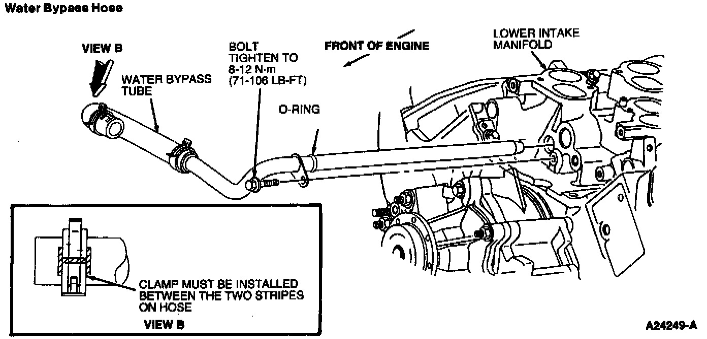
13. Remove water bypass tube retaining bolt.
14. Remove EGR valve (EGR valve) and adapter.
15. Remove lower intake manifold retaining bolts.
16. Remove lower intake manifold.
CAUTION: The lower intake manifold is sealed at each corner with sealer. To break the seal, it may be necessary to pry on the front of the intake manifold with a prybar. If it is necessary to pry on the lower intake manifold use care to prevent damage to machined surfaces.
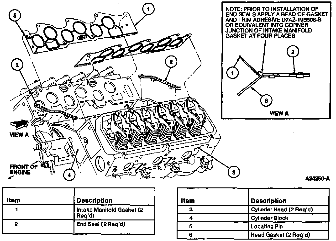
17. Remove intake manifold gasket and end seals, and discard.
18. If lower intake manifold assembly is to be disassembled, perform the following:
Part 1 Of 2:
Part 2 Of 2:
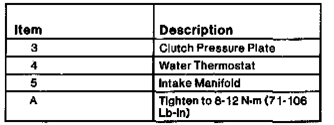
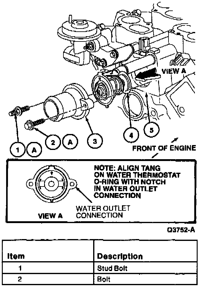
a. Remove water hose connection and water thermostat.
b. Remove water temperature indicator sender unit.
c. Remove engine coolant temperature sensor.
d. Remove vacuum controls.
INSTALLATION
1. The mating surfaces of the lower intake manifold, cylinder head, and cylinder block should be clean and free of old gasketing material.
NOTE: When using silicone rubber sealer, assembly must occur within 15 minutes after sealer application. After this time, the sealer may start to set-up, and its sealing effectiveness may be reduced.
2. Install new bushings into IMRC levers. If intake manifold was disassembled:
a. Apply a coat of Pipe Sealant with Teflon to the threads of the water temperature indicator sender unit and tighten to 8-13 Nm (71-115 inch lbs.).
b. Install engine coolant temperature sensor.
c. Install water thermostat (note direction). Install water hose connection. Tighten retaining bolt and stud bolt to 8-11 Nm (71-97 inch lbs.).
3. Apply a 3 mm (0.125 inch) bead of Silicone Rubber at each corner where the cylinder head joins the cylinder block.
NOTE:
- Prior to applying sealer, clean sealing surfaces of cylinder heads and lower intake manifold with Metal Surface Cleaner to remove all residues that may interfere with the sealer's ability to adhere.
- When the lower intake manifold is removed, always use new intake manifold gaskets upon reassembly.
4. Install front and rear intake manifold end seals.
5. Carefully install lower intake manifold into position on cylinder block and cylinder heads. Use locating pins if necessary to guide intake manifold.

6. Install bolts in their original locations. Tighten in numerical sequence as shown in the illustration in the Removal procedure to 8-12 Nm (71-106 inch lbs.).
NOTE: Prior to bolt installation, apply a coat of Pipe Sealant with Teflon to the threads of the lower intake manifold.
7. Install EGR valve and adapter assembly.
8. Install vacuum controls:
a. Install vacuum motor rod into new bushing.
b. Install two retaining bolts and tighten to 8-12 Nm (71-106 inch lbs.).
9. Install fuel injectors and fuel injection supply manifold. Tighten retaining bolts to 8-11 Nm (71-97 inch lbs.).
10. Install water bypass tube to lower intake manifold. Install and tighten retaining bolts to 8-11 Nm (71-97 inch lbs.).
11. Connect water bypass tube hose to heater water outlet tube. Install hose clamp securely.
12. Connect engine control sensor wiring to engine coolant temperature sensor, water temperature indicator sender unit and vacuum controls.
13. Connect vacuum lines to vacuum controls.
14. Connect upper radiator hose to water hose connection. Install hose clamp securely.
15. Install upper intake manifold.
16. Fill and bleed engine cooling system.
CAUTION: This engine has aluminum cylinder heads and requires a special corrosion inhibiting coolant to avoid cooling system damage.
17. Start engine and check for oil, coolant or fuel leaks.