Transmission Connector Layouts
For connector number and pin location, refer to the Wiring Diagram.1 Of 2:
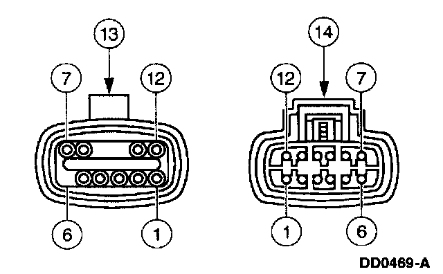
2 Of 2:
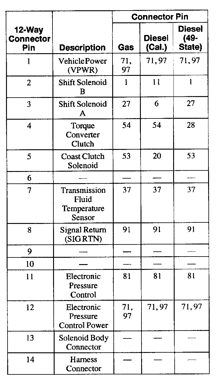
Transmission Vehicle Harness Connector
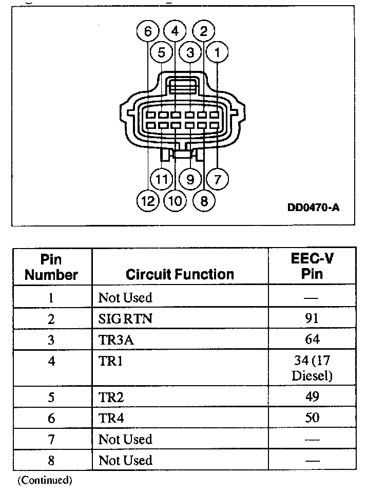
1 Of 2:
2 Of 2:
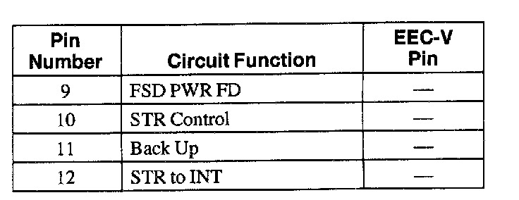
Digital Transmission Range (TR) Sensor Connector
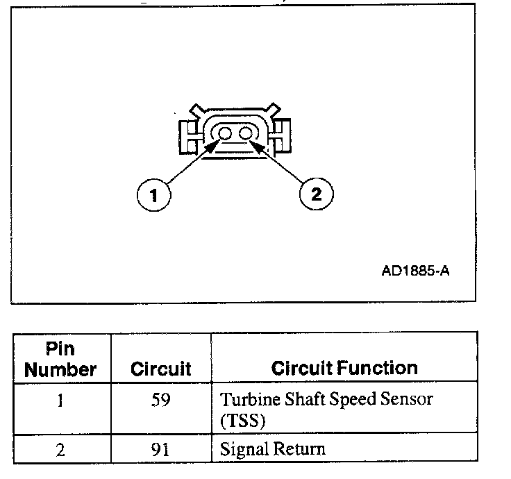
Turbine Shaft Speed Sensor (TSS) Harness Connector
1 Of 2:
2 Of 2:
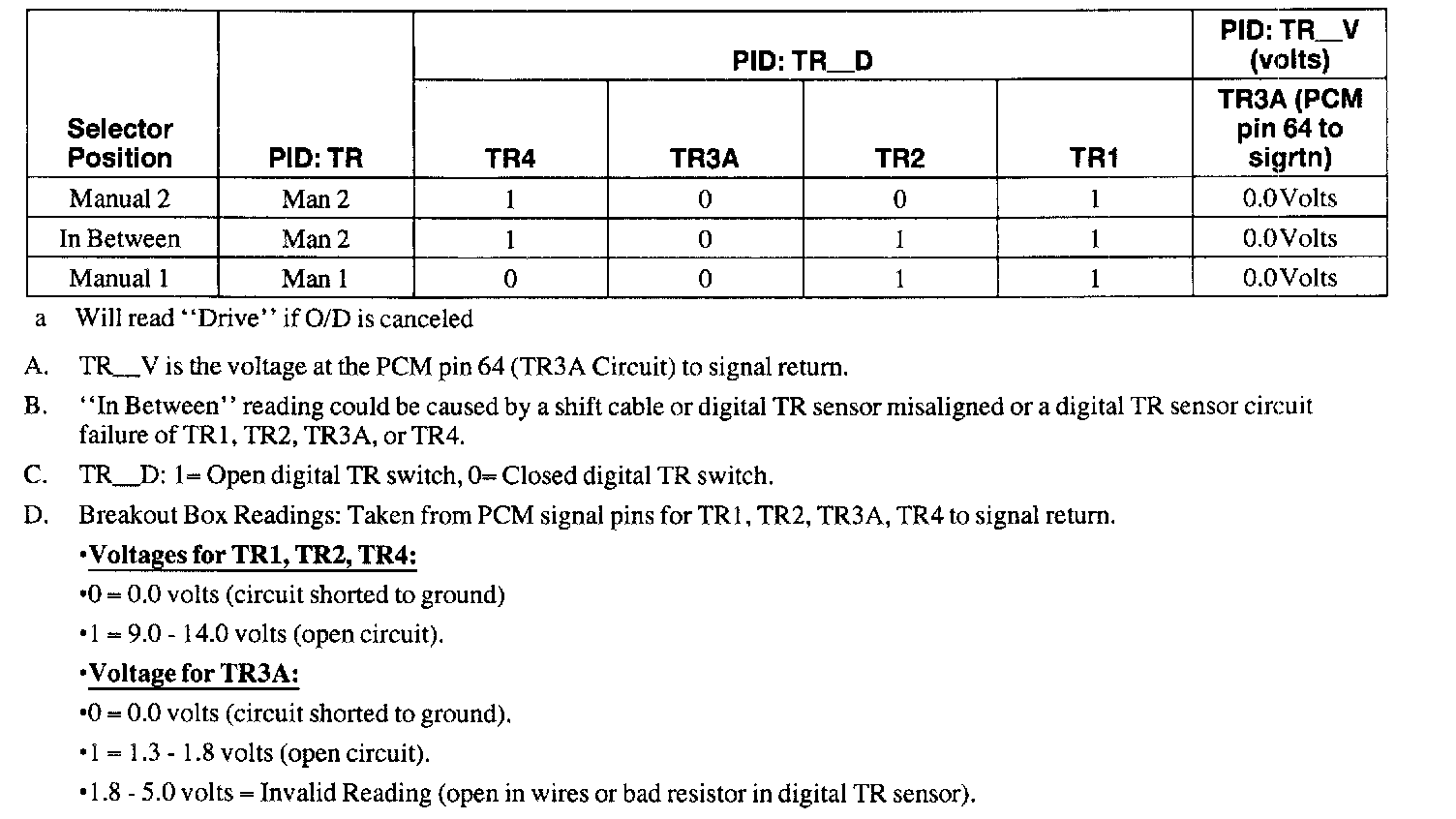
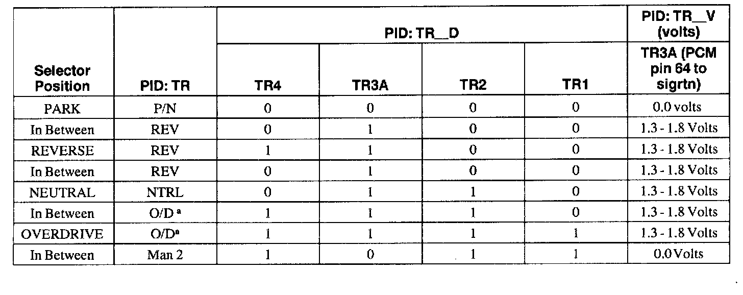
Digital Transmission Range (TR) Sensor Diagnosis Chart
a Will read "Drive" if O/D is canceled
A. TR_V is the voltage at the PCM pin 64 (TR3A Circuit) to signal return.
B. "In Between" reading could be caused by a shift cable or digital TR sensor misaligned or a digital TR sensor circuit failure of TR1, TR2, TR3A or TR4.
C. TR_D: 1-Open digital TR switch, 0-Closed digital TR switch.
D. Breakout Box Readings: Taken from PCM signal pins for TR1, TR2, TR3A, TR4 to signal return.
- Voltages for TR1, TR2, TR4:
- 0 = 0.0 volts (circuit shorted to ground)
- 1 = 9.0 - 14.0 volts (open circuit).
- Voltage for TR3A:
- 0 = 0.0 volts (circuit shorted to ground).
- 1 = 1.3 - 1.8 volts (open circuit).
- 1.8 - 5.0 volts = Invalid Reading (open in wires or bad resistor in digital TR sensor).