Differential Case: Service and Repair
Special Tools:
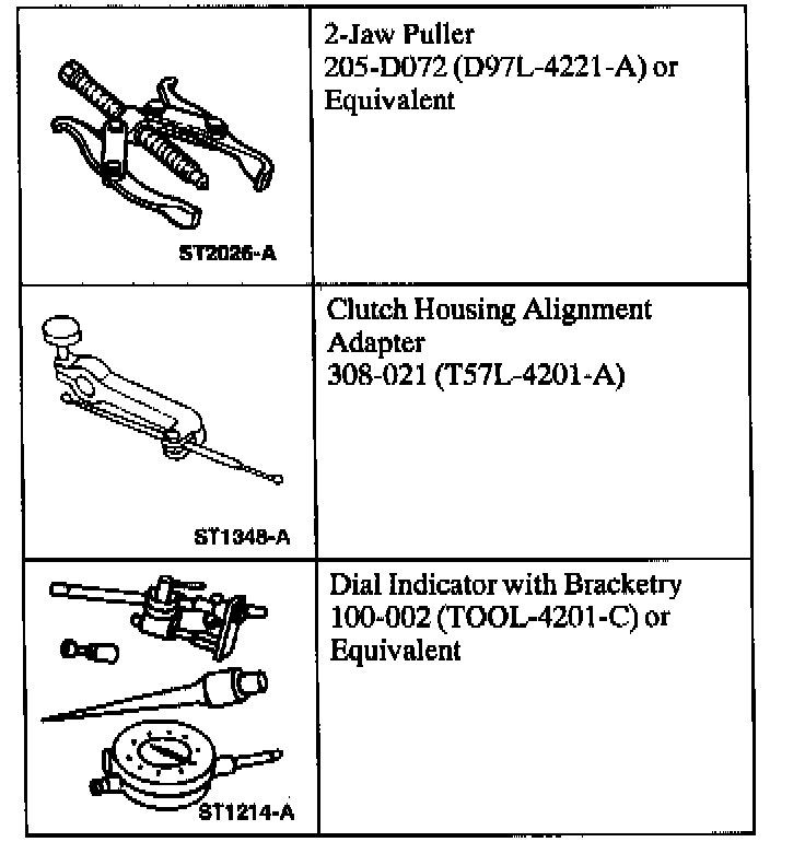
Special Tools:
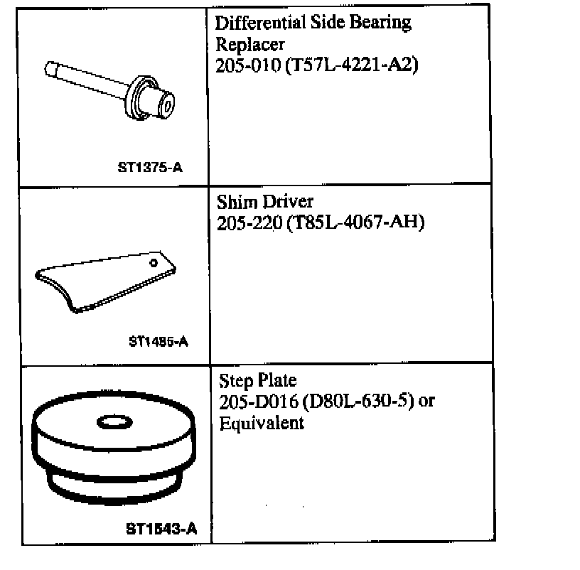
Removal
1. Remove the axle shafts.
2. Wipe the lubricant from the internal working parts and inspect the parts for wear and damage.
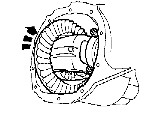
3. Rotate the differential assembly to check for roughness indicating bearing/gear damage.
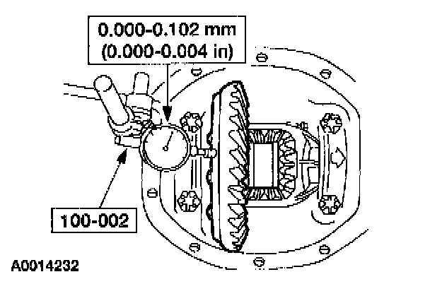
4. Using the special tool, measure and note the differential ring gear back face runout.
5. CAUTION: Mark the position of the differential bearing caps, as the arrows may not be visible. Always install the bearing caps in their identical locations and positions.
Remove the differential bearing caps.
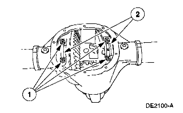
1 Remove the bolts.
2 Remove the differential bearing caps.
6. WARNING: Do not allow the differential assembly to fall.
CAUTION: Place a wood block between the pry bar and the differential housing to protect the machined surface from damage.
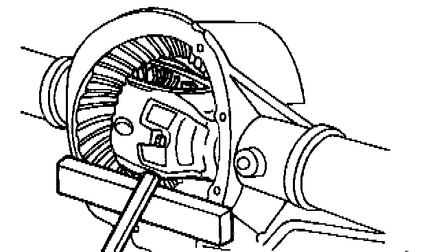
Using a pry bar and a wood block, remove the differential assembly from the differential housing.
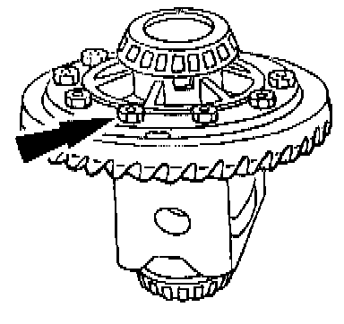
7. Remove the bolts.
8. CAUTION: Do not damage the differential ring gear bolt hole threads.
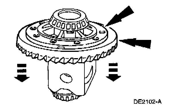
Insert a punch in the bolt holes, and drive off the differential ring gear.
9. If the differential ring gear back face runout measurement, taken at the beginning of this procedure, did not exceed the specification, proceed to the appropriate procedure as necessary, Drive Pinion, Differential Case and Ring Gear-Conventional or Differential Case and Ring Gear-Traction-Lok, or to Installation. If the differential ring gear back face runout measurement, taken at the beginning of this procedure, exceeded the specification, the cause may be a warped differential ring gear, differential case/differential bearing damage. Proceed as follows to verify the cause of the excessive runout.
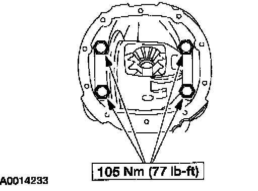
10. Position the differential assembly, including the differential bearing cups and differential bearing shims, in the differential housing. Install the differential bearing caps and the bolts.
11. Position the special tool.
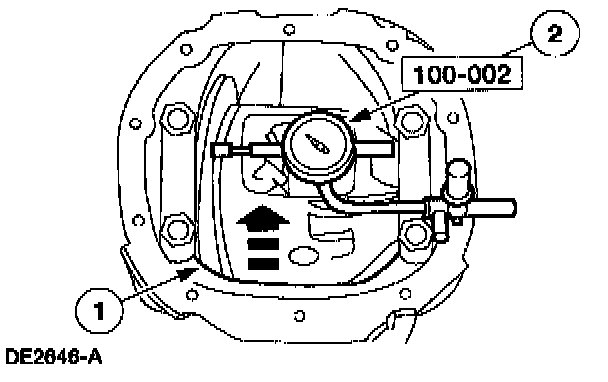
1 Rotate the differential case to verify that the differential bearings have seated correctly.
2 Position the special tool.
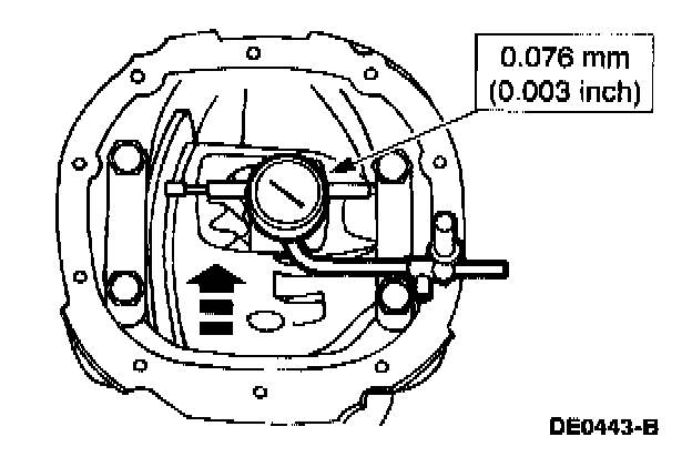
12. Measure and note the differential case runout.
- If the runout does not exceed the specification, install a new differential ring gear and pinion.
- If the runout exceeds the specification, the differential ring gear is true and the concern is due to either differential case/differential bearing damage. Proceed as follows.
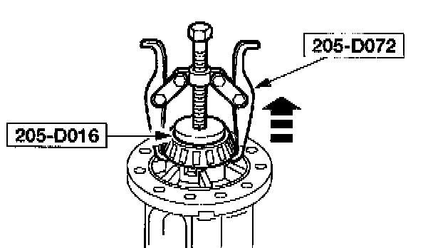
13. Using the special tools, remove the differential bearings.

14. Using the special tool, install the new differential bearings.
15. Position the differential assembly, including the differential bearing cups and differential bearing shims in the differential housing. Tighten differential bearing caps to specification.
16. Position the special tool.
1 Rotate the differential case to verify that the differential bearings have seated correctly.
2 Position the special tool.
17. Measure the differential case runout.
- If the runout does not exceed the specification, use the new differential bearings for assembly.
- If the runout exceeds the specification, install a new differential case.
Installation
All vehicles

1. Position the differential ring gear and the differential case. Align the bolt holes by starting two bolts through the holes in the differential case and the differential ring gear. Press the differential ring gear on the differential case.

2. Install the bolts.
- Apply Stud and Bearing Mount E0AZ-19554-BA or equivalent meeting Ford specification WSK-M2G349-A1 to the bolt threads.
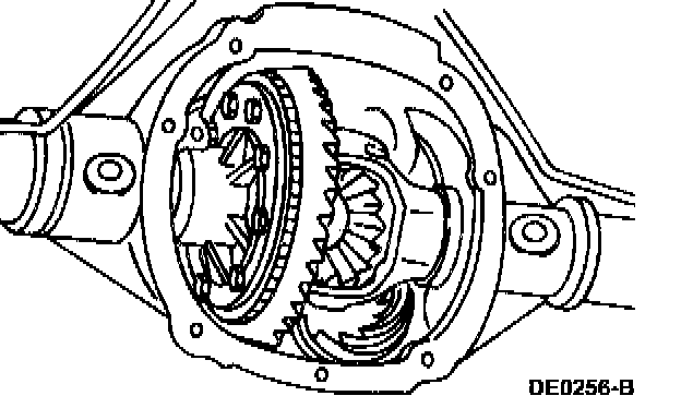
3. With the pinion depth set and pinion installed, place the differential assembly in the differential housing.
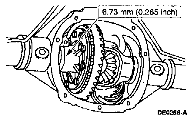
4. Install a differential bearing shim on the left side.
5. CAUTION: Always install the differential bearing caps in their identical locations and positions.
Note: Apply pressure toward the left side to make sure the left differential bearing cup seats correctly.
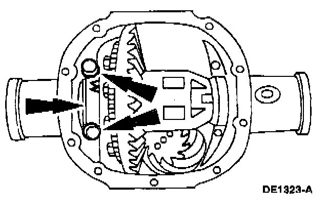
Install the left differential bearing cap and loosely install the bolts.
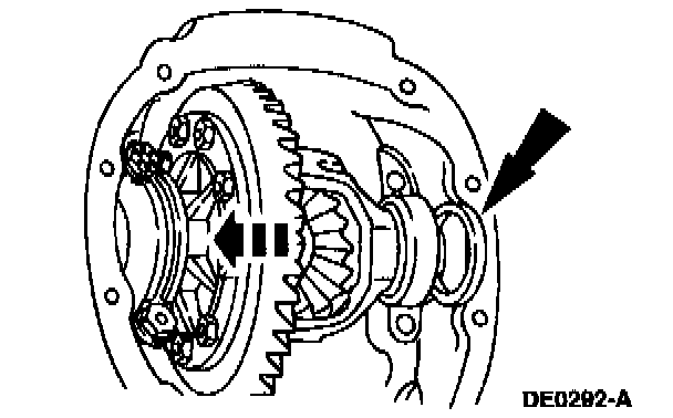
6. Install progressively larger differential bearing shims on the right side until the largest shim selected is installed by hand.
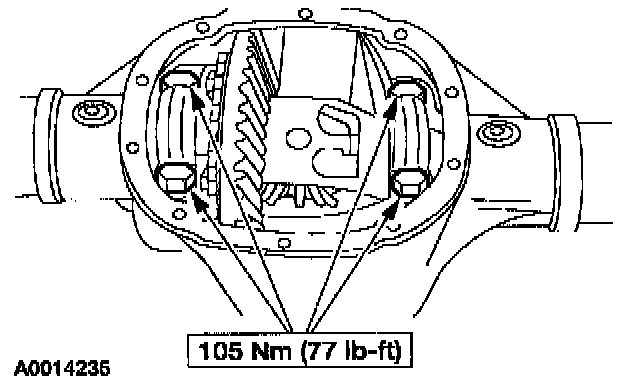
7. Install the right side differential bearing cap and tighten the left side and right side bolts to specification.
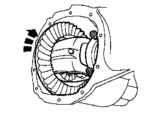
8. Rotate the differential case to make sure it turns freely.
Measuring backlash
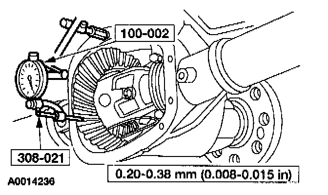
9. Using the special tools, measure and note the differential ring gear backlash.
- If backlash is within the specification. The specification shown is the full allowable range.
- If a zero backlash condition occurs, refer to Zero backlash.
- If backlash is not within the specification, refer to Backlash not within specification.
Zero backlash

10. If a zero backlash condition occurs, add 0.51 mm (0.020 inch) to the RH side and subtract 0.51 mm (0.020 inch) from the LH side to allow backlash indication. Measure the backlash.
Backlash not within specification
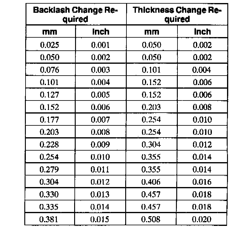
11. To increase or decrease backlash, remove the differential bearing caps and install a thicker shim and a thinner shim accordingly.
- If backlash is not within the specification, increase the thickness of one differential bearing shim and decrease the thickness of the other differential bearing shim by the same amount.
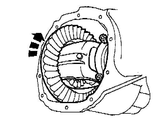
12. Rotate the differential assembly several times to verify that the differential bearings seated correctly.
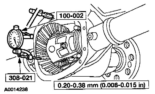
13. Using the special tools, recheck the backlash.
- If backlash is within the specification, refer to Backlash within specification. If backlash is not within the specification, repeat Backlash not within specification.
- The specification shown is the full allowable range.
Backlash within specification
14. Remove the bolts and the differential bearing caps.
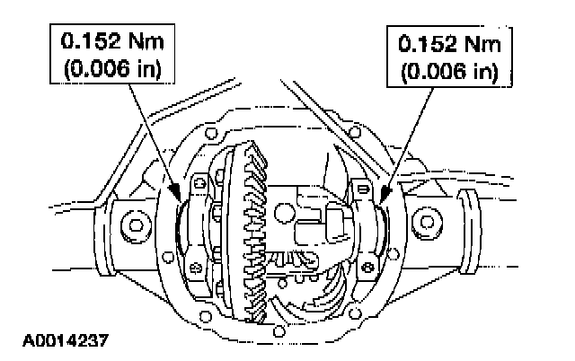
15. To establish differential bearing preload, increase both left and right differential bearing shim sizes by the specification shown.
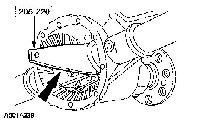
16. Using the special tool, fully seat the differential bearing shims. Make sure the assembly rotates freely.
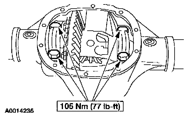
17. Install the differential bearing caps and bolts.
18. Using the special tools, recheck the backlash.
- The specification shown is the full allowable range.
19. Install the axle shafts.