Driver Air Bag Module
Special Tool(s):

SPECIAL TOOL(S)
REMOVAL
WARNING:
^ ALWAYS WEAR SAFETY GLASSES WHEN REPAIRING AN AIR BAG SUPPLEMENTAL RESTRAINT SYSTEM (SRS) VEHICLE AND WHEN HANDLING AN AIR BAG MODULE. THIS WILL REDUCE THE RISK OF INJURY IN THE EVENT OF AN ACCIDENTAL DEPLOYMENT.
^ CARRY A LIVE AIR BAG MODULE WITH THE AIR BAG AND TRIM COVER POINTED AWAY FROM YOUR BODY. THIS WILL REDUCE THE RISK OF INJURY IN THE EVENT OF AN ACCIDENTAL DEPLOYMENT.
^ DO NOT SET A LIVE AIR BAG MODULE DOWN WITH THE TRIM COVER FACE DOWN. THIS WILL REDUCE THE RISK OF INJURY IN THE EVENT OF AN ACCIDENTAL DEPLOYMENT.
^ CARRY A LIVE AIR BAG MODULE (SOFT PACK) POINTED AWAY FROM YOUR BODY. THIS WILL REDUCE THE RISK OF INJURY IN THE EVENT OF AN ACCIDENTAL DEPLOYMENT.
^ AFTER DEPLOYMENT, THE AIR BAG SURFACE CAN CONTAIN DEPOSITS OF SODIUM HYDROXIDE, A PRODUCT OF THE GAS GENERANT COMBUSTION THAT IS IRRITATING TO THE SKIN. WASH YOUR HANDS WITH SOAP AND WATER AFTERWARDS.
^ NEVER PROBE THE CONNECTORS ON THE AIR BAG MODULE. DOING SO CAN RESULT IN AIR BAG DEPLOYMENT, WHICH CAN RESULT IN PERSONAL INJURY.
^ AIR BAG MODULES WITH DISCOLORED OR DAMAGED TRIM COVERS MUST BE REPLACED, NOT REPAINTED.
NOTE:
^ The driver air bag (soft pack) and steering wheel can be serviced separately or as an assembly.
^ In the event of an air bag (soft pack) deployment, the air bag (soft pack) and steering wheel must be serviced as an assembly.
^ Repair is made by installing a new part only. If the new part does not correct the condition, install the original part and perform the diagnostic procedure again.
1. Prepare the vehicle for driver air bag module removal.
1 Disconnect the battery ground cable and wait at least one minute.
WARNING:
^ TO AVOID ACCIDENTAL DEPLOYMENT AND POSSIBLE PERSONAL INJURY, THE BACKUP POWER SUPPLY MUST BE DEPLETED BEFORE REPAIRING OR REPLACING ANY FRONT OR SIDE AIR BAG SUPPLEMENTAL RESTRAINT SYSTEM (SRS) COMPONENTS AND BEFORE SERVICING, REPLACING, ADJUSTING OR STRIKING COMPONENTS NEAR THE FRONT OR SIDE AIR BAG SENSORS, SUCH AS DOORS, INSTRUMENT PANEL, CONSOLE, DOOR LATCHES, STRIKERS, SEATS AND HOOD LATCHES.
^ PLEASE REFER TO THE APPROPRIATE COMPONENT OR SYSTEM TO DETERMINE LOCATION OF THE FRONT AIR BAG SENSORS.
^ THE SIDE AIR BAG SENSORS ARE LOCATED AT OR NEAR THE BASE OF THE B-PILLAR.
^ TO DEPLETE THE BACKUP POWER SUPPLY ENERGY, DISCONNECT THE BATTERY GROUND CABLE AND WAIT AT LEAST ONE MINUTE. BE SURE TO DISCONNECT AUXILIARY BATTERIES AND POWER SUPPLIES (IF EQUIPPED).
2 Deactivate the Supplemental Restraint System (SRS).
WARNING: TO REDUCE THE RISK OF SERIOUS PERSONAL INJURY, READ AND FOLLOW ALL WARNINGS, CAUTIONS, NOTES, AND INSTRUCTIONS IN THE SUPPLEMENTAL RESTRAINT SYSTEM (SRS) DEACTIVATION/REACTIVATION PROCEDURE. Refer to Air Bag(s) Arming and Disarming.
2. Remove the steering wheel.
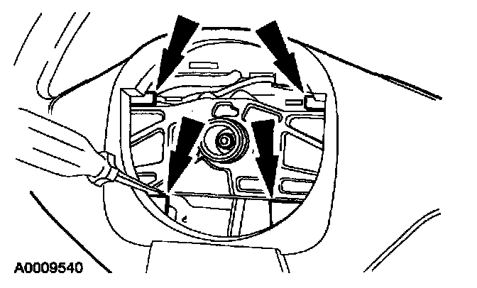
3. Release the retaining tabs. Remove the steering wheel rear cover.
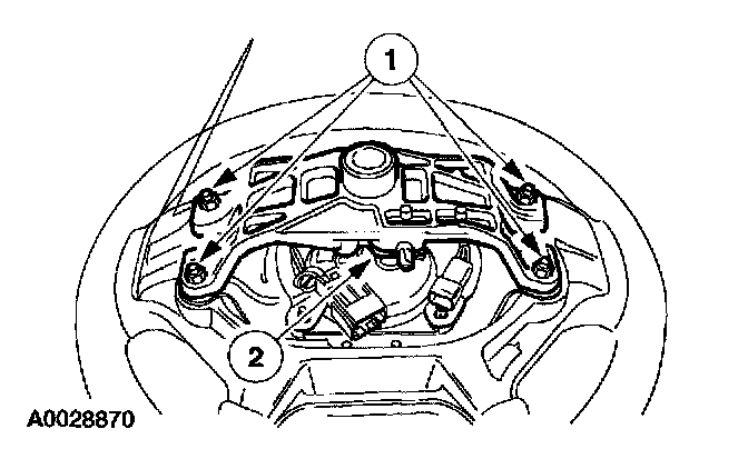
4. Remove the steering wheel armature.
1 Remove the nuts.
2 Remove the steering wheel armature.
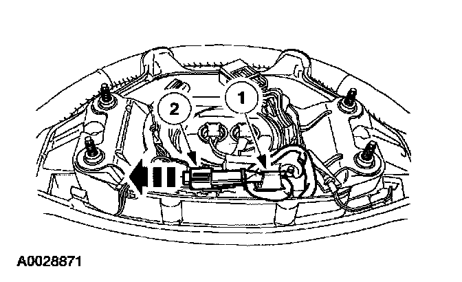
5. Disconnect the horn electrical connector.
1 Remove the horn wire harness from the wire shield retaining clip.
2 Slide the horn electrical connector off of the wire shield. Disconnect the horn electrical connector.
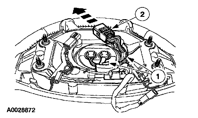
6. Remove the driver air bag module electrical connector and wire harness from the wire shield.
1 Remove the driver air bag module wire harness from the wire shield retaining clips.
2 Releasing the retaining tab, remove the driver air bag module electrical connector from the wire shield.
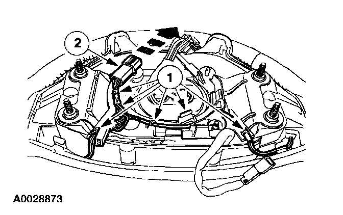
7. Remove the component feed electrical connector from the wire shield.
1 Remove the component feed wire harness from the wire shield retaining clips.
2 Slide the component feed electrical connector off the wire shield.
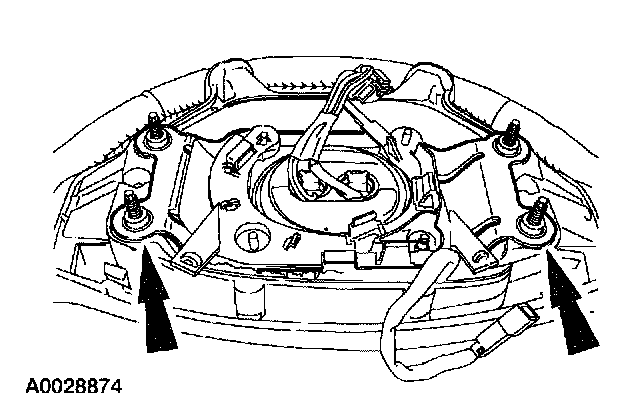
8. Carefully prying up between the air bag module backing plate and the steering wheel, remove the driver air bag module.
NOTE: Position any wire harnesses or electrical connectors out of the way prior to removing the driver air bag module.
INSTALLATION
WARNING: TO REDUCE THE RISK OF SERIOUS PERSONAL INJURY, READ AND FOLLOW ALL WARNINGS, CAUTIONS AND NOTES AT THE BEGINNING OF THE REMOVAL PROCEDURE.
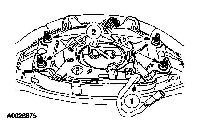
1. Position the air bag module (soft pack) into the steering wheel.
1 While positioning the air bag module into the steering wheel, route the horn switch wire harness and connector out between the air bag module (soft pack) and the steering wheel, so that any extra horn switch wire harness is not in the steering wheel cavity.
2 Position the air bag module so that the steering wheel positioning sleeves go through the air bag module backing plate alignment holes and the air bag module backing plate lies flat on the steering wheel all the way around.
WARNING:
^ WHEN INSTALLING A DRIVER AIR BAG MODULE (SOFT PACK), MAKE SURE THERE ARE NO FOREIGN OBJECTS IN THE STEERING WHEEL CAVITY OR IN THE DRIVER AIR BAG MODULE (SOFT PACK). FAILURE TO DO SO MAY RESULT IN PERSONAL INJURY IN THE EVENT OF AN AIR BAG DEPLOYMENT.
^ DO NOT DISLODGE THE FABRIC FROM THE AIR BAG MODULE (SOFT PACK). IN THE EVENT THAT THE AIR BAG FABRIC BECOMES DISLODGED, INSTALL A NEW AIR BAG MODULE (SOFT PACK). FAILURE TO DO SO MAY RESULT IN PERSONAL INJURY IN THE EVENT OF AN AIR BAG DEPLOYMENT.
^ BE CAREFUL NOT TO PINCH THE AIR BAG FABRIC BETWEEN THE STEERING WHEEL AND THE AIR BAG MODULE HOUSING. IN THE EVENT THE FABRIC BECOMES PINCHED INSTALL A NEW AIR BAG MODULE (SOFT PACK). FAILURE TO DO SO MAY RESULT IN THE AIR BAG NOT FUNCTIONING PROPERLY.
^ MAKE SURE THE HORN WIRING (RED CONNECTOR) IS ROUTED OUT BETWEEN THE TWO AIR BAG (SOFT PACK) MOUNTING EARS. FAILURE TO DO SO MAY RESULT IN THE AIR BAG (SOFT PACK) NOT FUNCTIONING PROPERLY.
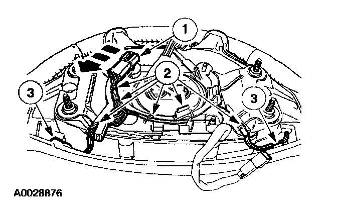
2. Install the component feed electrical connector and wire harness onto the wire shield.
1 Slide the component feed electrical connector onto the wire shield.
2 Route the component feed wire harness between the wire shield retaining clips.
3 Route the remaining wire harness into the steering wheel wire retainers.
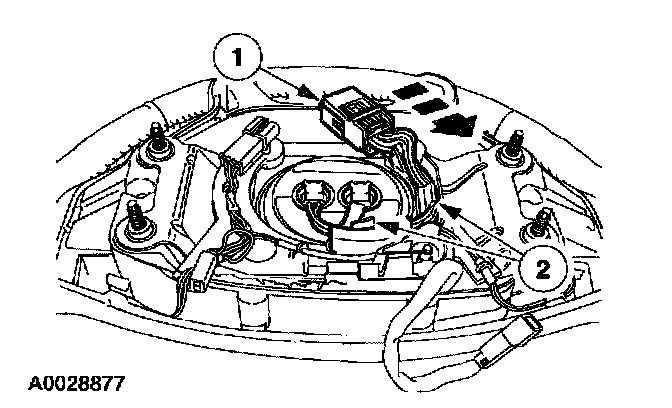
3. Install the driver air bag module electrical connector and wire harness onto the wire shield.
1 Slide the driver air bag module electrical connector onto the wire shield.
2 Route the driver air bag module wire harness between the wire shield retaining clips.
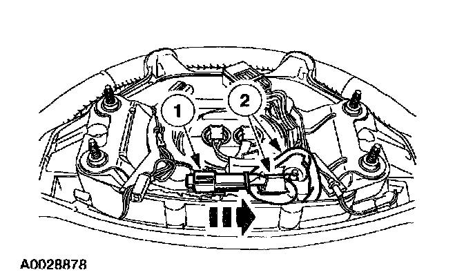
4. Install the horn electrical connector and wire harness onto the wire shield.
1 Connect the horn electrical connector. Slide the horn electrical connector onto the wire shield.
2 Route the horn wire harness between the wire shield retaining clip.

5. Position the steering wheel armature onto the steering wheel.
1 Make sure that none of the extra horn switch wire harness has fallen back into the steering wheel cavity.
2 Make sure that the air bag module backing plate lies flat on the steering wheel all the way around.
3 Make sure that there are not any wires between the air bag module backing plate and the steering wheel armature mating surfaces.
4 Align the steering wheel armature onto the steering wheel with the worm gear bolt head facing the two electrical connectors.
5 Install the nuts.
CAUTION: Make sure the horn wiring is routed out between the air bag backing plate and the steering wheel. Failure to do so may result in the air bag not deploying correctly.
NOTE: The steering wheel armature will only go on the steering wheel one way.
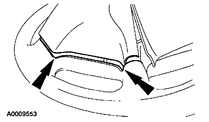
6. Install the steering wheel rear cover onto the steering wheel.
^ Make sure that the steering wheel rear cover is seated all the way around in the steering wheel mating groove.
7. Install the steering wheel. Do not connect the large driver air bag module electrical connector at this time.
WARNING: TO REDUCE THE RISK OF SERIOUS PERSONAL INJURY, READ AND FOLLOW ALL WARNINGS, CAUTIONS, NOTES, AND INSTRUCTIONS IN THE STEERING WHEEL REMOVAL AND INSTALLATION PROCEDURE.
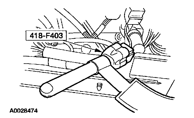
8. Remove the restraint system diagnostic tool from the vehicle harness side of the clockspring electrical connector.
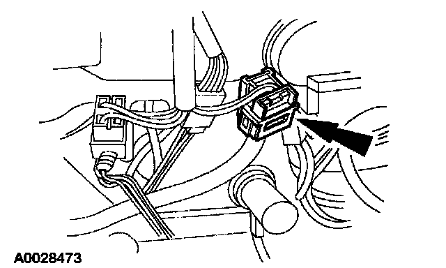
9. Connect the clockspring electrical connector at the base of the steering column.
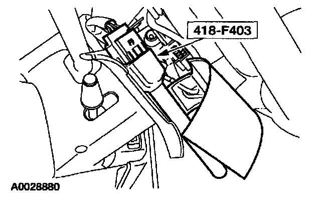
10. Through the steering wheel access door, attach the restraint system diagnostic tool to the clockspring electrical connector at the top of the steering column.
11. Connect the battery ground cable.
12. With the restraint system diagnostic tools installed at all deployable devices, prove out the supplemental restraint system (SRS). Prove Out Procedure
13. Disconnect the battery ground cable and wait at least one minute.
14. Remove the restraint system diagnostic tool from the clockspring electrical connector at the top of the steering column.

15. Through the steering wheel access door, connect the driver air bag module electrical connector. Close the steering wheel access door.
16. Connect the battery ground cable.
17. With the restraint system diagnostic tools still installed at the remaining deployable devices, prove out the supplemental restraint system (SRS). Prove Out Procedure
18. Disconnect the battery ground cable and wait at least one minute.
WARNING:
^ TO AVOID ACCIDENTAL DEPLOYMENT AND POSSIBLE PERSONAL INJURY, THE BACKUP POWER SUPPLY MUST BE DEPLETED BEFORE REPAIRING OR REPLACING ANY FRONT OR SIDE AIR BAG SUPPLEMENTAL RESTRAINT SYSTEM (SRS) COMPONENTS AND BEFORE SERVICING, REPLACING, ADJUSTING OR STRIKING COMPONENTS NEAR THE FRONT OR SIDE AIR BAG SENSORS, SUCH AS DOORS, INSTRUMENT PANEL, CONSOLE, DOOR LATCHES, STRIKERS, SEATS AND HOOD LATCHES.
^ PLEASE REFER TO THE APPROPRIATE COMPONENT OR SYSTEM TO DETERMINE LOCATION OF THE FRONT AIR BAG SENSORS.
^ THE SIDE AIR BAG SENSORS ARE LOCATED AT OR NEAR THE BASE OF THE B-PILLAR.
^ TO DEPLETE THE BACKUP POWER SUPPLY ENERGY, DISCONNECT THE BATTERY GROUND CABLE AND WAIT AT LEAST ONE MINUTE. BE SURE TO DISCONNECT AUXILIARY BATTERIES AND POWER SUPPLIES (IF EQUIPPED).
19. Restore the vehicle to operating condition.
1 With all the restraint system diagnostic tools removed, prove out the supplemental restraint system (SRS). Prove Out Procedure
WARNING: TO REDUCE THE RISK OF SERIOUS PERSONAL INJURY, READ AND FOLLOW ALL WARNINGS, CAUTIONS, NOTES, AND INSTRUCTIONS IN THE SUPPLEMENTAL RESTRAINT SYSTEM (SRS) DEACTIVATION/REACTIVATION PROCEDURE. REACTIVATE THE SUPPLEMENTAL RESTRAINT SYSTEM (SRS). Refer to Air Bag(s) Arming and Disarming.
2 With all the restraint system diagnostic tools removed, prove out the supplemental restraint system (SRS). Prove Out Procedure
WARNING: THE RESTRAINT SYSTEM DIAGNOSTIC TOOL IS FOR RESTRAINT SYSTEM SERVICE ONLY. REMOVE FROM THE VEHICLE PRIOR TO ROAD USE. FAILURE TO REMOVE COULD RESULT IN INJURY AND POSSIBLE VIOLATION OF VEHICLE SAFETY STANDARDS.