Valve Body: Service and Repair
Main Control-Pump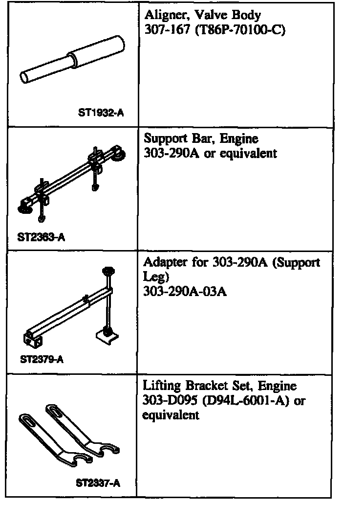
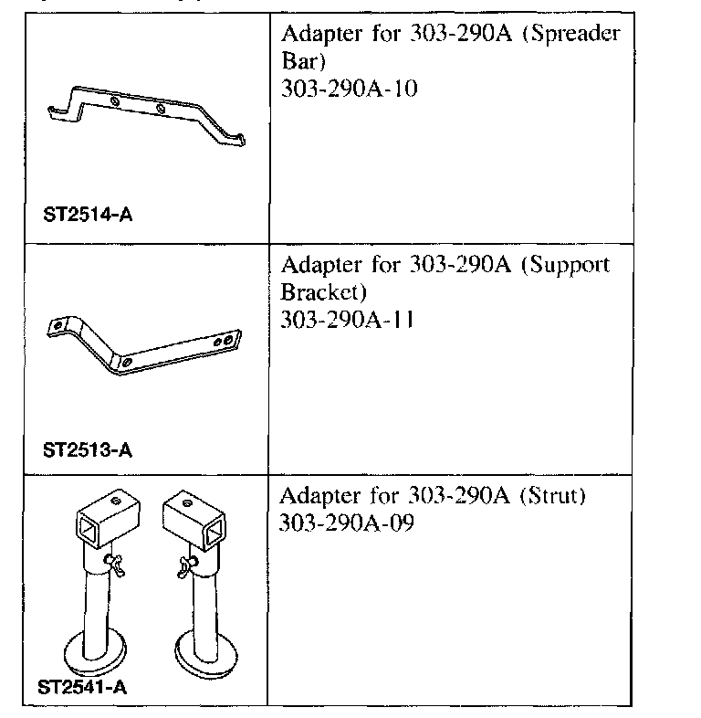
Special Tool(s)
Removal
1. Place the transaxle range selector lever in the PARK position.
2. Remove the engine air cleaner assembly.
3. NOTE: When the battery is disconnected and reconnected, some abnormal drive symptoms may occur while the vehicle relearns its adaptive strategy.
Disconnect the battery.
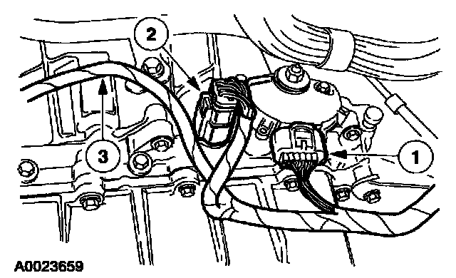
4. Disconnect the electrical connectors.
1 Disconnect the digital Transmission Range (TR) sensor electrical connector.
2 Disconnect the transaxle electrical connector.
3 Disconnect the wire harness from the bracket.
5. Remove the wiper arm and pivot assembly.
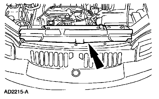
6. Remove the front upper radiator shield.
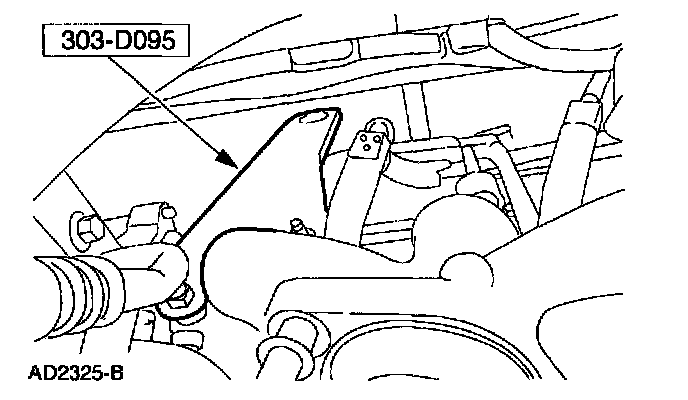
7. Install the special tool.
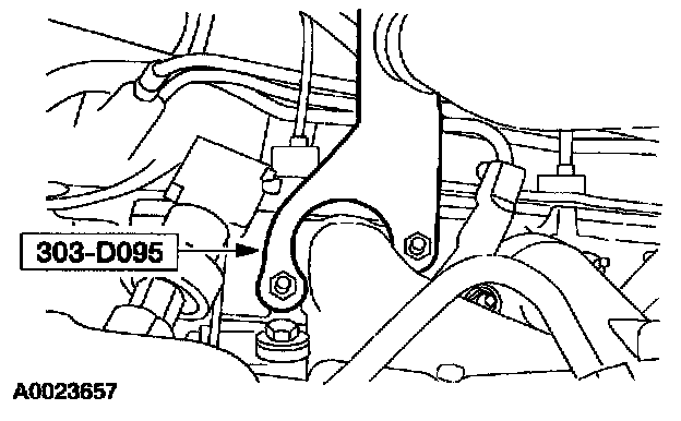
8. Install the special tool.
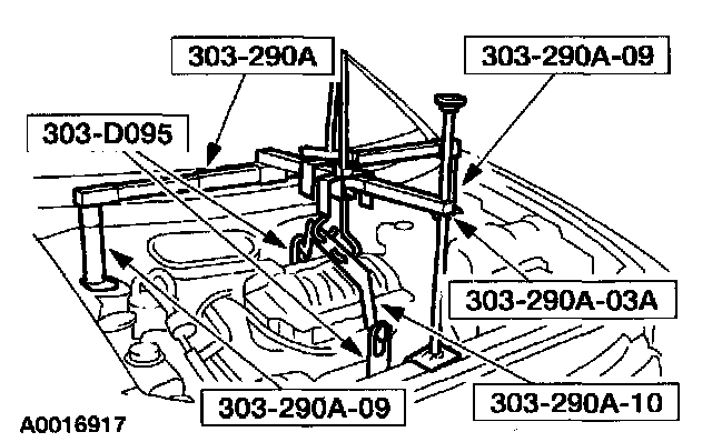
9. Install the special tools.
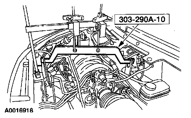
10. Install the special tool.
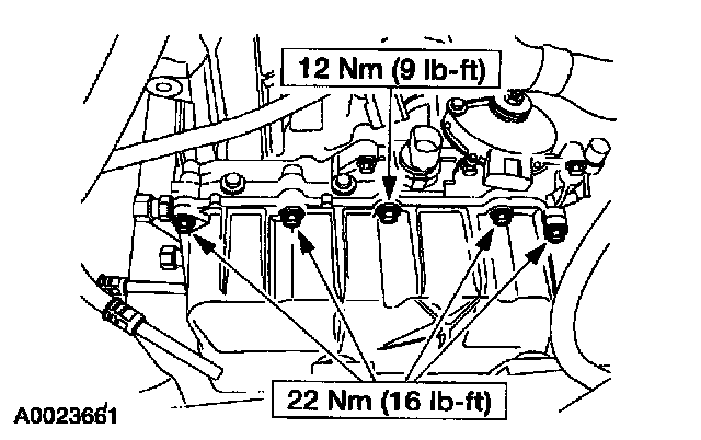
11. Remove the upper main control cover bolts.
12. Raise and support the vehicle.
13. Remove the LH wheel and tire.
14. Remove the LH transaxle support and insulator.
15. Position a drain pan under the transaxle side pan.
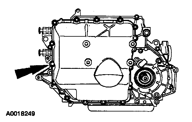
16. NOTE: It will be necessary to lower the left side of the subframe to remove the main control cover through the wheel well.
Remove the remaining bolt main control cover.
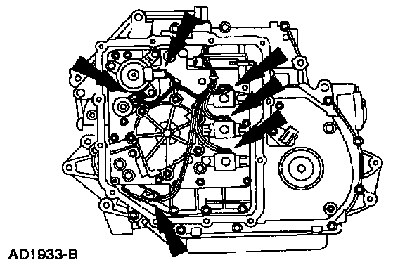
17. CAUTION: Do not pull on the wires or the electrical connectors. Damage to the connectors will result.
Lift the locking tab and disconnect the electrical connectors.
18. Position the transaxle wiring harness out of the way.
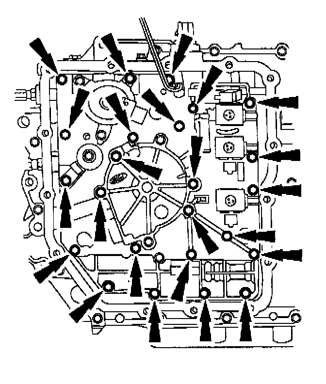
19. CAUTION: Do not remove the two bolts that hold the pump assembly and main control valve body together as the pump assembly may fall from the main control valve body and become damaged.
CAUTION: Only four of the six bolts need to be removed.
Remove the bolts. Note the size and location of the bolts.
20. Disconnect the manual linkage.

21. Remove the main pump assembly and the main control valve body by carefully sliding it off the pump shaft.
Installation
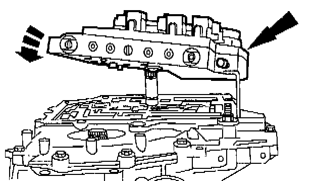
1. Install the pump assembly and main control valve body onto the pump shaft.
2. Rotate the pump assembly and main control valve body to connect the manual valve link with the manual valve.
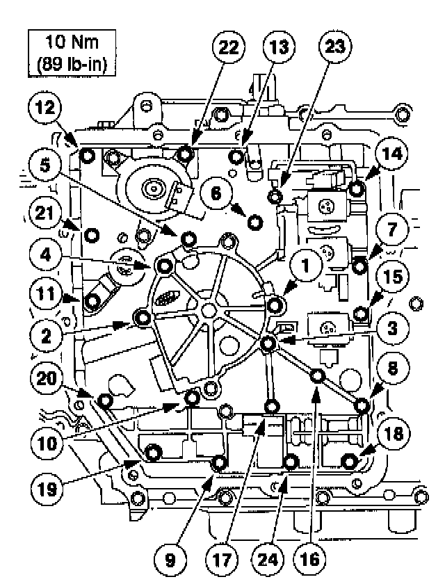
3. CAUTION: Do not use the bolts to draw pump assembly and main control valve body onto the chain cover case. Component damage may occur.
Using the Valve Body Aligner, install the pump assembly and main control valve body. Install the retaining bolt.
4. Install the transaxle wire harness and retaining clip into the separator plate.
5. Connect the electrical connectors.
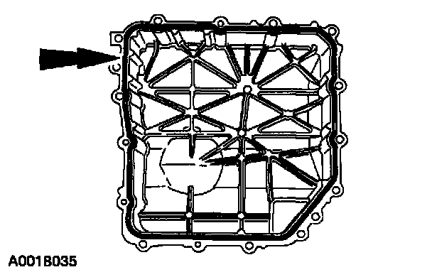
6. NOTE: The transaxle side cover gasket is reusable if not torn or ripped.
Remove the gasket. Clean and inspect the gasket, reinstall into the pan.
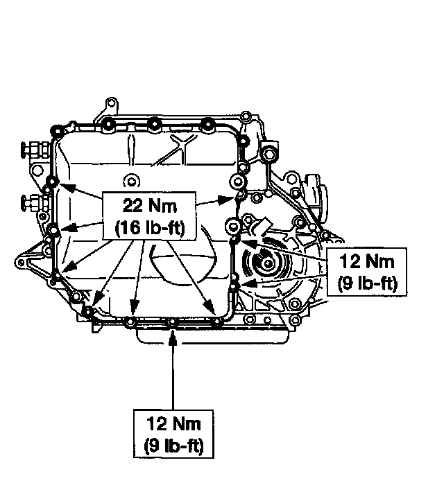
7. NOTE: After the cover has been installed, it may be necessary to raise the subframe back into place if it had been lowered.
Install the side cover, gasket and bolts.
8. Install the LH transaxle support and insulator.
9. Install the LH wheel and tire.
10. Lower the vehicle.
11. Install the upper main control cover bolts.
12. Remove the special tool.
13. Remove the special tools.
14. Remove the special tool.
15. Remove the special tool.
16. Connect the electrical connectors.
1 Connect the digital Transmission Range (TR) sensor electrical connector.
2 Connect the transaxle electrical connector.
3 Connect the wire harness into the bracket.
17. Install the wiper arm and pivot assembly.
18. Install the engine air cleaner inlet assembly.
19. NOTE: When the battery is disconnected and reconnected, some abnormal drive symptoms may occur while the vehicle relearns its adaptive strategy.
Connect the battery.
20. Fill the transaxle assembly with one quart of MERCON V Automatic Transmission Fluid XT-5-QM meeting Ford specification MERCON V.
21. Start the engine. Move the transaxle range selector lever through all positions. Check the fluid level.