Intake Manifold: Service and Repair
Intake Manifold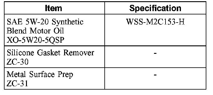
Material
Removal
WARNING: Do not smoke or carry lighted tobacco or open flame of any type when working on or near any fuel-related components. Highly flammable mixtures are always present and can be ignited, resulting in possible personal injury.
WARNING: Fuel in the fuel system remains under high pressure, even when the engine is not running. Do not work on any fuel system component until fuel system pressure has been relieved. Failure to follow these instructions may result in personal injury.
1. Relieve the fuel system pressure.
2. Disconnect the battery ground cable.
3. Drain the engine cooling system.
4. Remove the engine cover.
5. Remove the air cleaner and the air cleaner outlet tube.
6. Remove the generator.
7. Disconnect the fuel tube spring lock coupling.
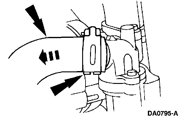
8. Compress and slide the hose clamp and disconnect the coolant hose.
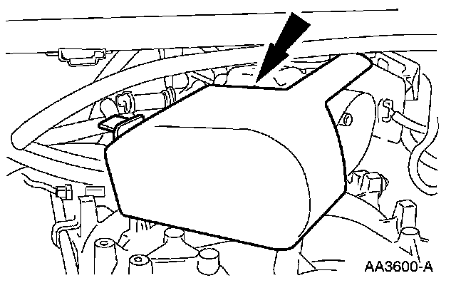
9. Remove the accelerator cable splash shield.3
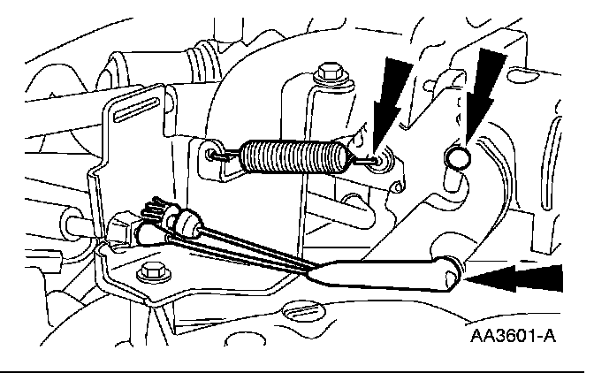
10. Disconnect the accelerator and speed control cables and remove the return spring.
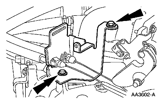
11. Position the accelerator cable bracket aside.
^ Remove the bolts.
^ Position the bracket and cables aside.
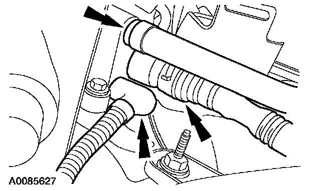
12. Disconnect the heated positive crankcase valve (PCV) tube and the vacuum hoses.
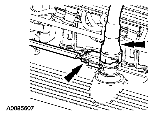
13. Disconnect the PCV electrical connector and tube.
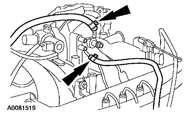
14. Disconnect the PCV coolant hoses.
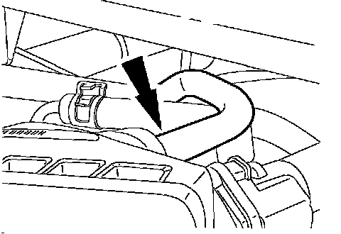
15. Disconnect the vacuum tube.
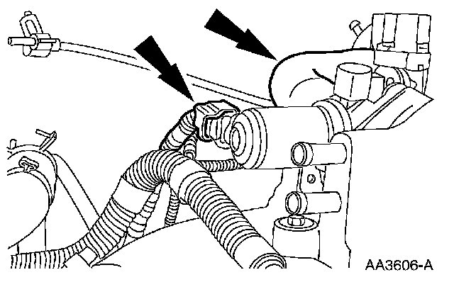
16. Disconnect the idle air control (IAC) motor electrical connector and remove the bypass hose.
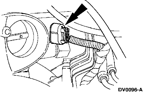
17. Disconnect the throttle position (TP) sensor electrical connector.
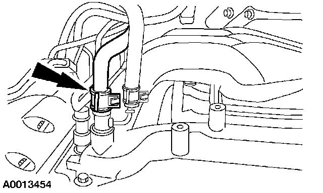
18. Disconnect the heater hose.
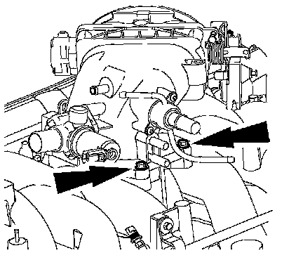
19. Remove the throttle body (TB) adapter.
^ Remove the four bolts.
^ Remove the TB adapter.
^ Discard the TB adapter press-in-place gasket.
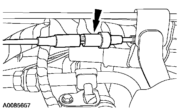
20. Disconnect the vacuum connector.
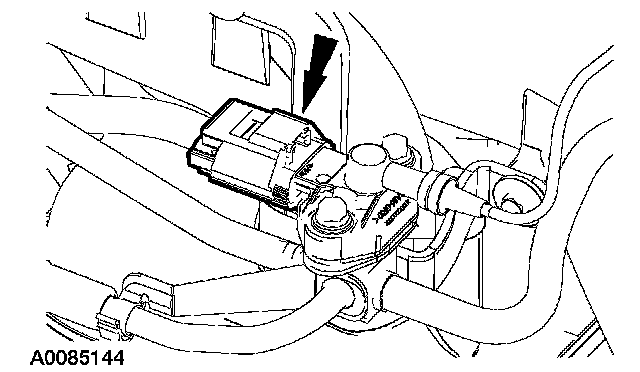
21. Disconnect the fuel rail pressure (FRP) sensor electrical connector.
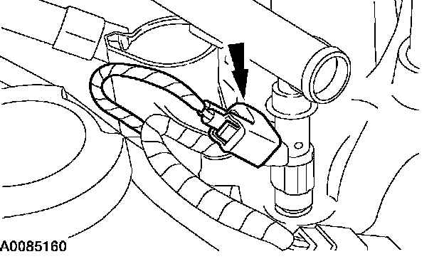
22. Disconnect the ten fuel injector electrical connectors.
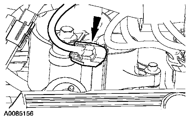
23. Disconnect the ten ignition coil electrical connectors.
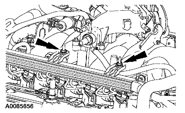
24. Remove the nuts and position the RH fuel charge wiring harness aside.
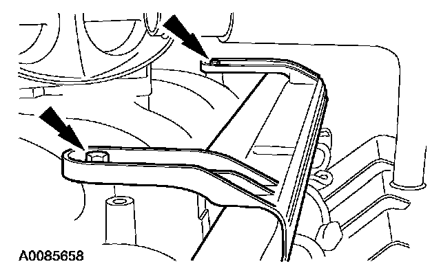
25. Remove the nuts and position the LH fuel charge wiring harness aside.
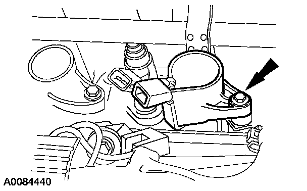
26. Remove the ten bolts and the ten ignition coils.
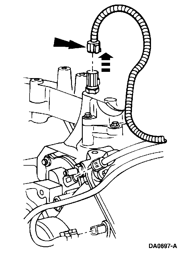
27. Disconnect the engine coolant temperature (ECT) sensor electrical connector.
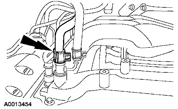
28. Disconnect the heater hose.
29. Remove the water thermostat and housing.
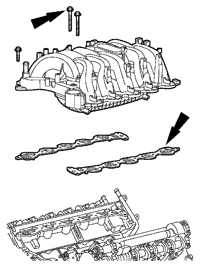
30. Remove the bolts, the upper intake manifold and the intake manifold gaskets. Discard the intake manifold gaskets.
31. CAUTION: Do not use metal scrapers, wire brushes, power abrasive discs or other abrasive means to clean the aluminum retainer plate. These tools cause scratches and gouges, which make leak paths.
Clean all mating surfaces.
^ Clean the intake manifold mating surface of the cylinder heads with silicone gasket remover and metal surface prep. Follow the directions on the packaging.
Installation

1. NOTE: Tighten the bolts in two stages.
Tighten the bolts in the sequence shown.
^ Stage 1: Tighten to 2 Nm (18 inch lbs.).
^ Stage 2: Tighten to 10 Nm (89 inch lbs.).
2. Position the water thermostat and housing.
^ Install a new O-ring seal.

3. Install the upper intake manifold.
^ Position the new upper intake manifold gaskets and the intake manifold, and loosely install the bolts.

4. Tighten the bolts in two stages, in the sequence shown.
^ Stage 1: Tighten to 2 Nm (18 inch lbs.).
^ Stage 2: Tighten to 25 Nm (18 ft. lbs.).
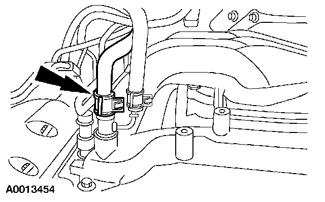
5. Connect the heater hose.
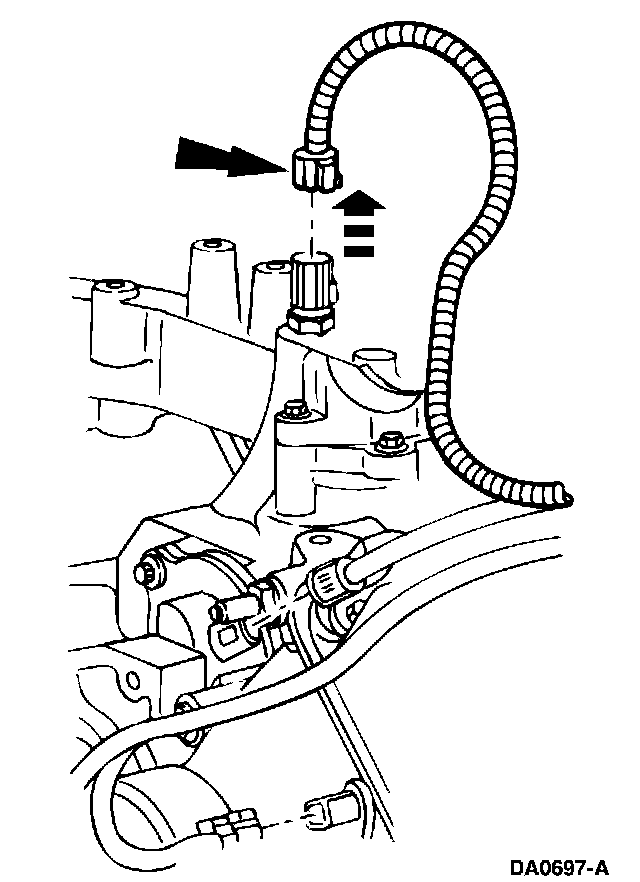
6. Connect the ECT sensor electrical connector.
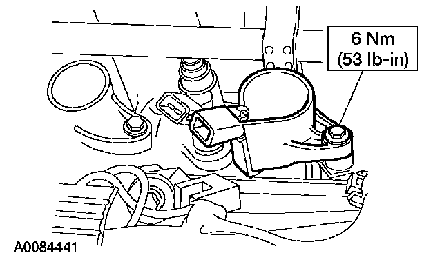
7. Install the ten bolts and the ten ignition coils.
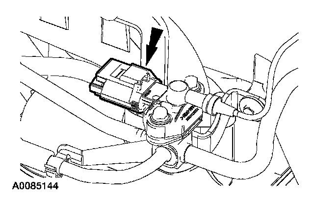
8. Connect the FRP sensor electrical connector.
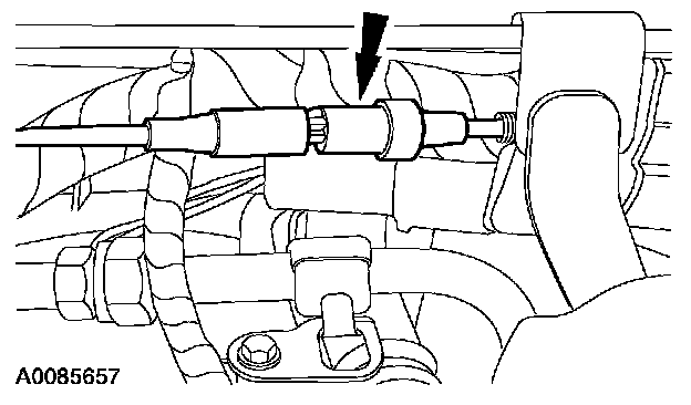
9. Connect the vacuum connector.

10. Install the TB adapter.
1. Install a new TB adapter gasket.
2. Position the TB adapter.
3. Install the four bolts and tighten in two stages.
^ Stage 1: Tighten the bolts to 9 Nm (80 inch lbs.).
^ Stage 2: Tighten an additional 90 degrees.
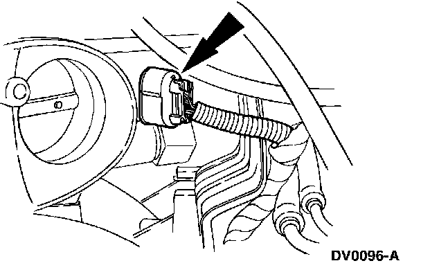
11. Connect the TP sensor electrical connector.
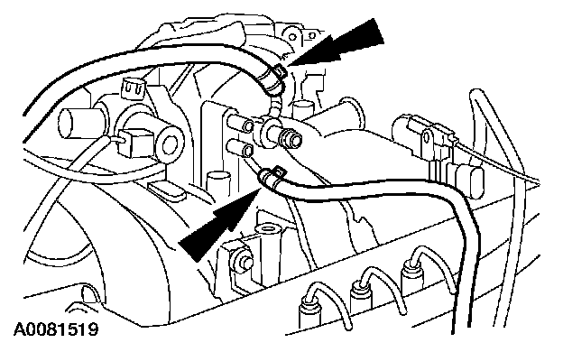
12. Connect the PCV coolant hoses.
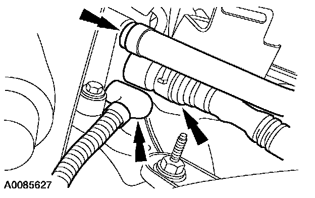
13. Connect the heated PCV tube and the vacuum hoses.
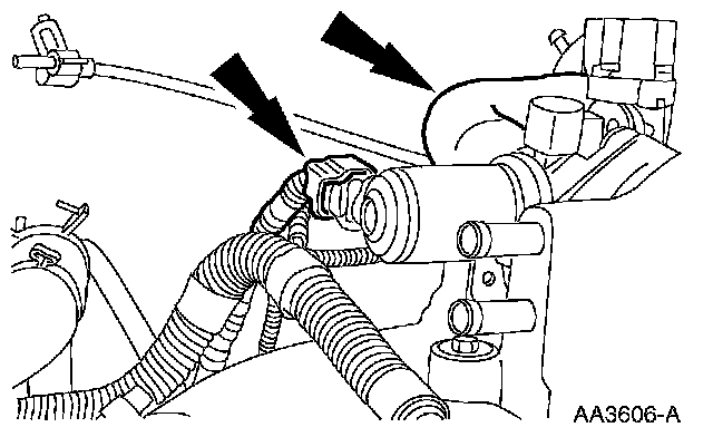
14. Connect the IAC motor electrical connector and install the bypass hose.
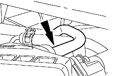
15. Connect the vacuum tube.
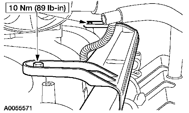
16. Position the LH fuel charge wiring harness and install the nuts.
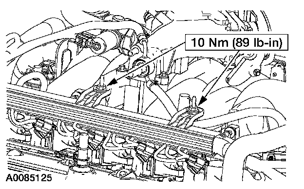
17. Position the RH fuel charge wiring harness and install the nuts.
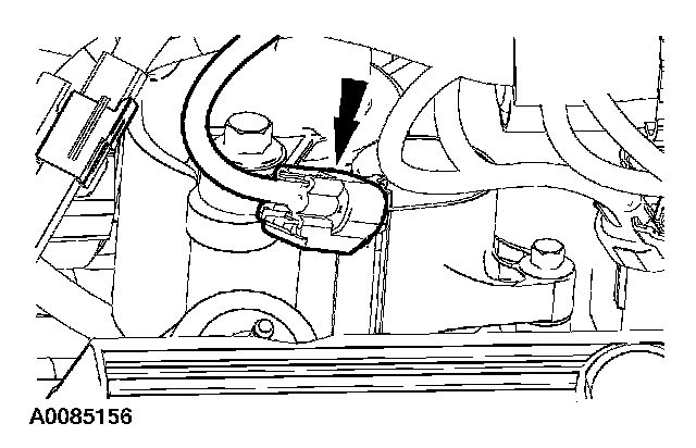
18. Connect the ten ignition coil electrical connectors.
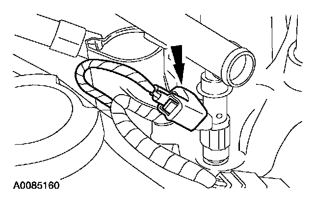
19. Connect the ten fuel injector electrical connectors.
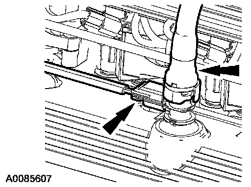
20. Install the PVC tube and connect the electrical connector.
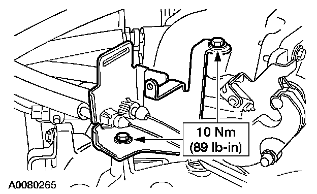
21. Install the accelerator bracket.
^ Position the bracket.
^ Install the bolts.
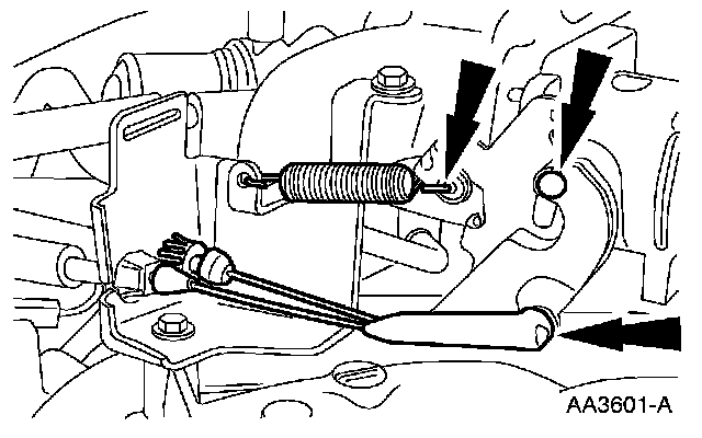
22. Connect the accelerator and speed control cables and return spring.
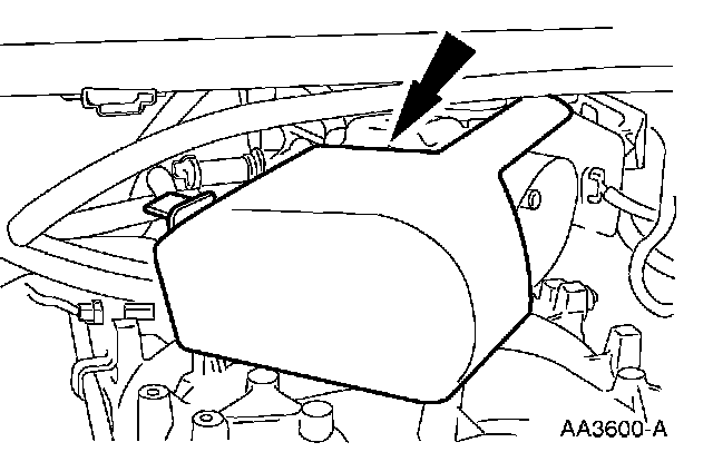
23. Install the accelerator cable splash shield.
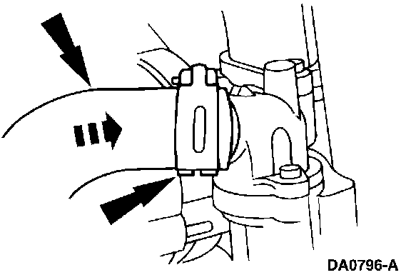
24. Connect the coolant hose and position the hose clamp.
25. Connect the fuel tube spring lock coupling.
26. Install the generator.
27. Install the air cleaner and the air cleaner outlet tube.
28. Install the engine cover.
29. Connect the battery ground cable.
30. Fill and bleed the engine cooling system.