Steps 1 - 50
NOTE: Ford does not provide a TDC (Top Dead Center) mark or determination procedure for this engine in this vehicle.
ALLDATA users have reported success using aftermarket tools to determine TDC on this engine.
DISASSEMBLY
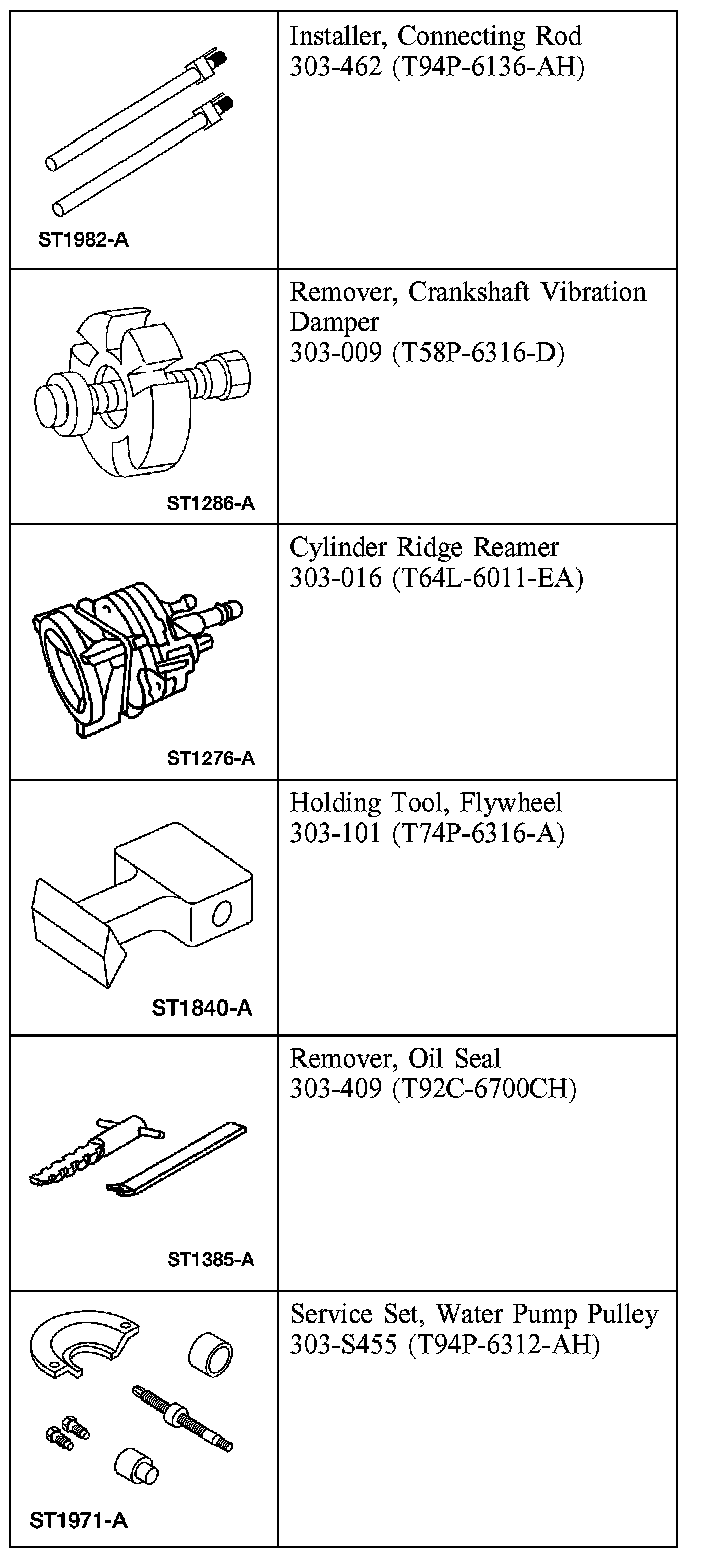
Special Tool(s)
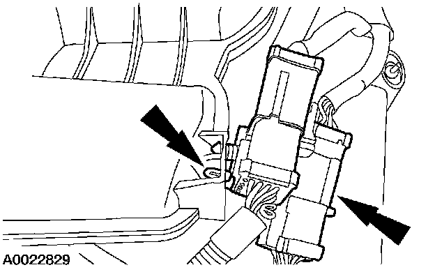
All vehicles
1. Separate the engine control sensor wiring connectors from the upper intake manifold.
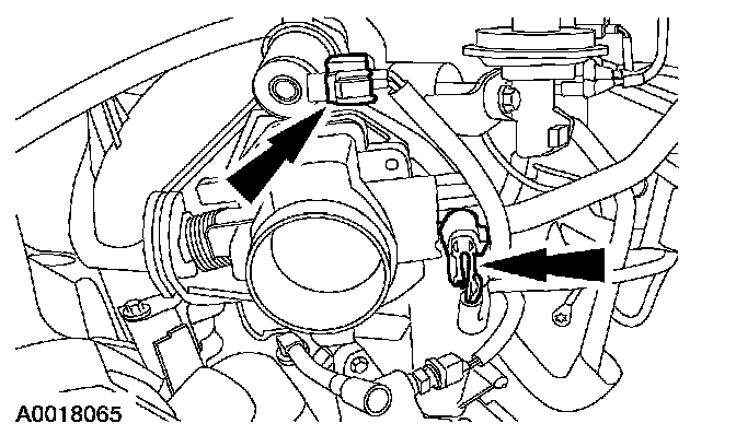
2. Disconnect the idle air control (IAC) valve and the throttle position (TP) sensor electrical connectors.
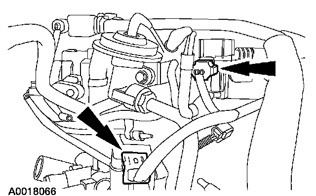
3. Disconnect the exhaust gas recirculation (EGR) vacuum regulator solenoid and the differential pressure feedback EGR system electrical connectors.
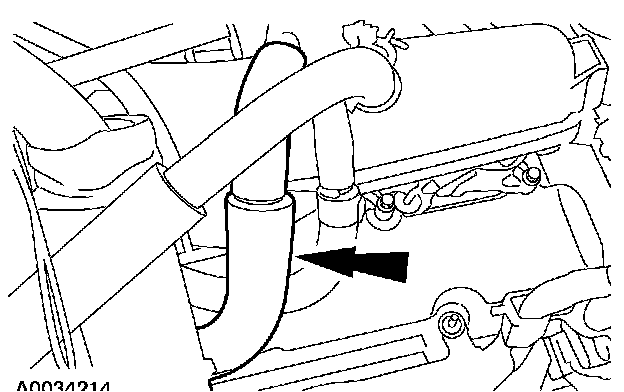
4. Remove the positive crankcase ventilation (PCV) tube.
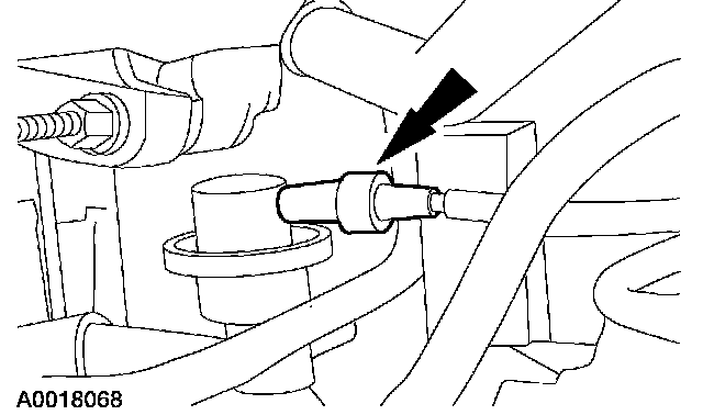
5. Disconnect the vacuum hose from the fuel pressure regulator.
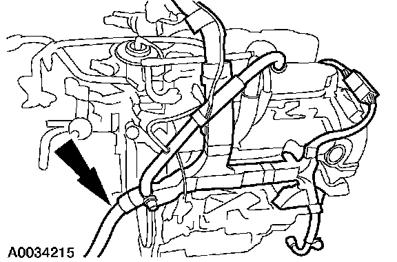
6. Disconnect and remove the engine control wire harness.
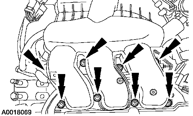
7. Remove the bolts and upper intake manifold.
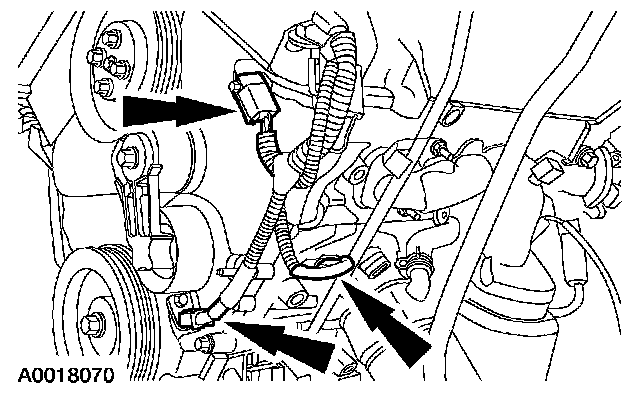
8. Disconnect the crankshaft and camshaft position sensor electrical connectors.
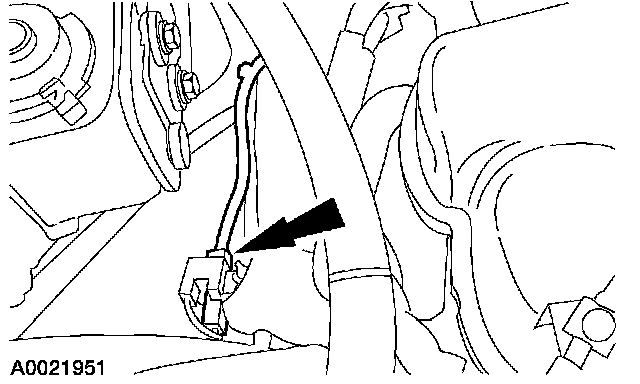
9. Disconnect the radio ignition interference capacitor electrical connectors.
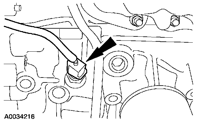
10. Disconnect the engine coolant temperature (ECT) sensor and the oil pressure switch.
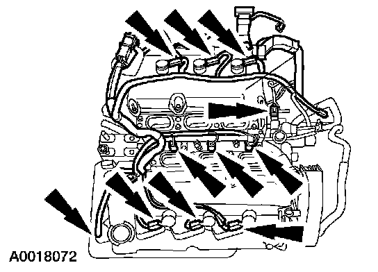
11. Disconnect the remaining electrical connectors and harness retainers and remove the harness.
12. CAUTION: When removing the coil-on-plugs, a slight twisting motion will break the seal and ease removal.
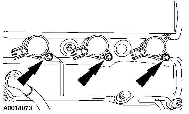
Remove the bolts and the six coil-on-plugs.
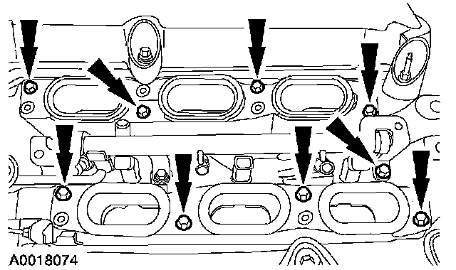
13. Remove the lower intake manifold and discard the gaskets.
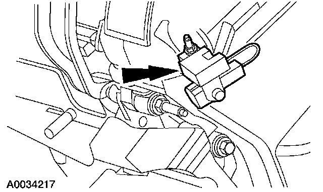
14. Remove the nut and the radio interference capacitors.
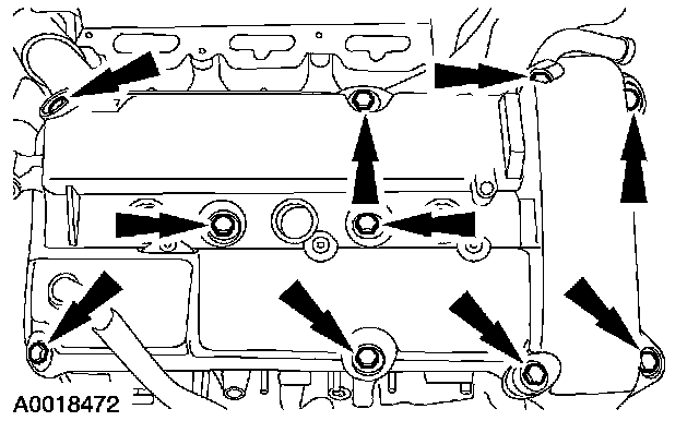
15. Remove the RH valve cover.
- Remove and discard the gasket.
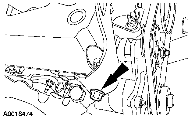
16. Remove the engine lift bracket.
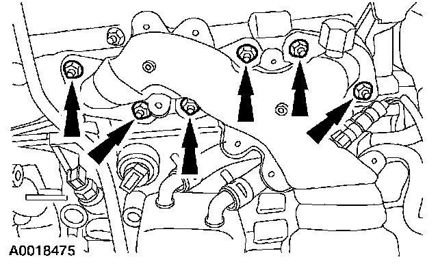
17. Remove the nuts, the LH exhaust manifold and the gasket. Discard the gasket.
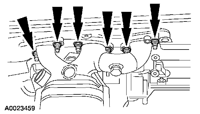
18. Remove the nuts, the RH exhaust manifold and the gasket. Discard the gasket.
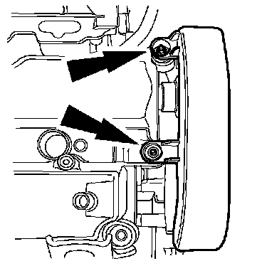
19. Remove the water pump belt cover.
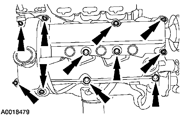
20. Remove the LH valve cover.
- Remove and discard the gasket.

Vehicles equipped with water pump belt tensioner
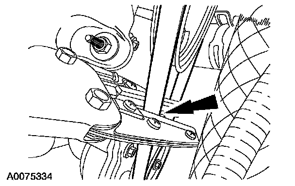
21. Rotate the belt tensioner clockwise and remove the water pump belt.
Vehicles not equipped with water pump belt tensioner
22. Cut and remove the water pump belt. Discard the belt.
All vehicles
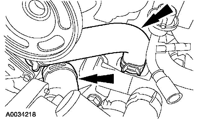
23. Disconnect the hoses.
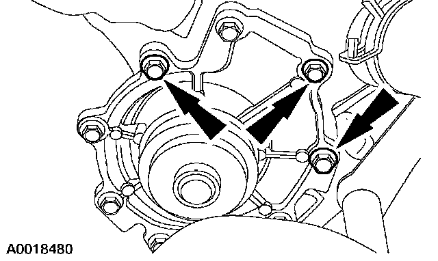
24. Remove the water pump assembly.
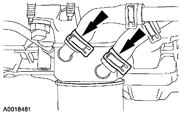
25. Disconnect the coolant hoses at the oil cooler.
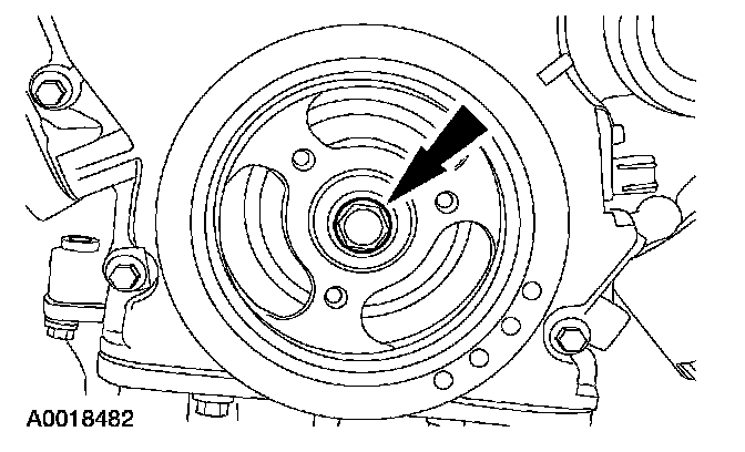
26. Remove the bolt.
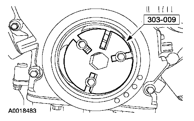
27. Using the special tool, remove the crankshaft damper.
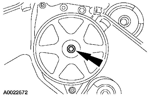
28. Remove the power steering pump pulley.
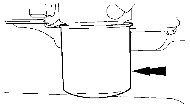
29. Remove and discard the oil filter.
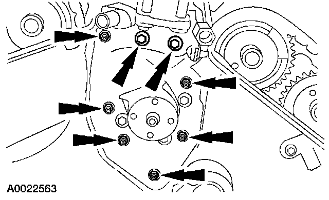
30. Remove the power steering pump.
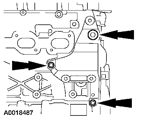
31. Remove the generator support bracket.
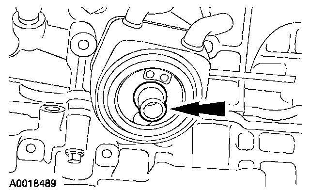
32. Remove the oil cooler.
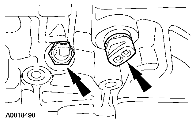
33. Remove the oil pressure sender and the block heater.
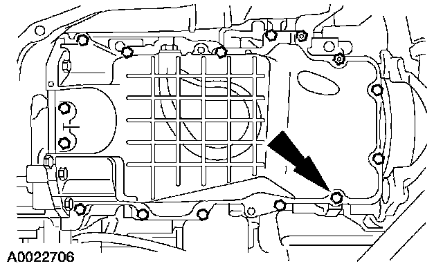
34. Remove the bolts and studs and the oil pan.
- Discard the gasket.
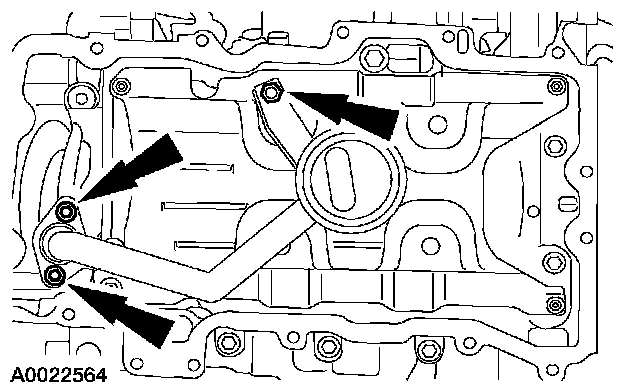
35. Remove the bolts, nut and the oil pump screen and pickup tube.
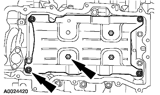
36. Remove the nuts and the oil pan baffle.
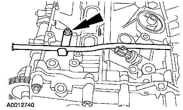
37. Remove the stud bolt and the oil level indicator and tube.
38. CAUTION: Do not use metal scrapers, wire brushes, power abrasive discs or other abrasive means to clean the sealing surface. These tools cause scratches and gouges, which make leak paths. Use a plastic scraping tool to remove all traces of sealant.
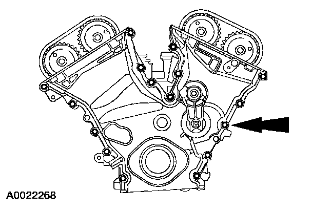
Remove the bolts, studs, and the front cover.
- Discard the gasket.
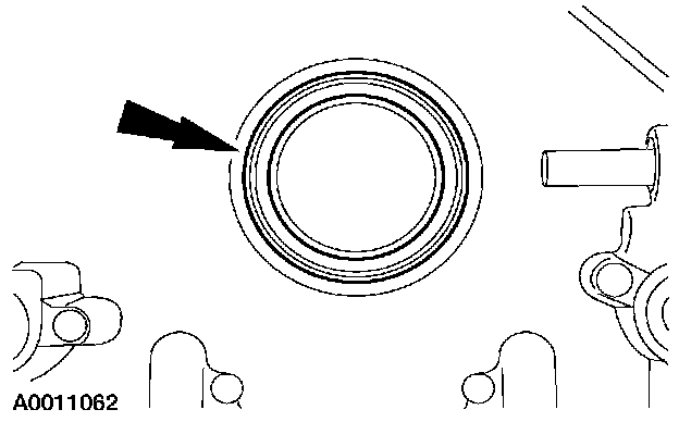
39. Remove and discard the crankshaft front seal from the front cover.
40. CAUTION: This pulse wheel is used in several different engines. Install the pulse wheel with the keyway in the slot stamped 20-25-34Y-30M (Color Blue).
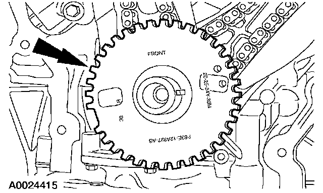
Remove the ignition pulse wheel.
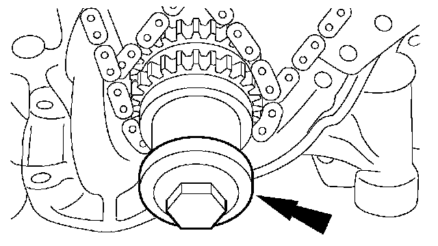
41. Install the damper bolt.
42. NOTE: RH shown; LH similar.
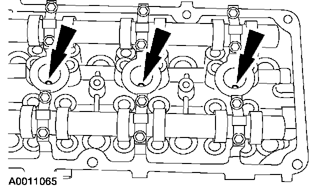
Remove the LH and RH spark plugs.
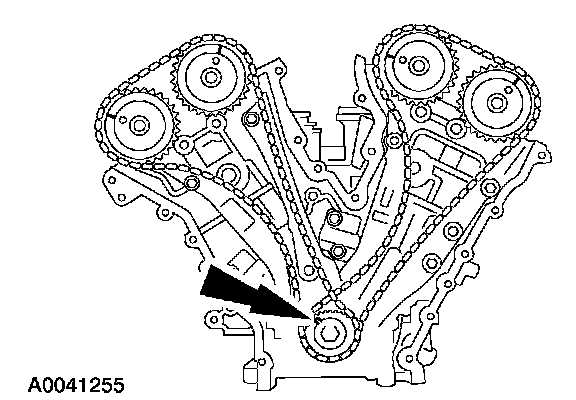
43. Rotate the crankshaft clockwise to position the crankshaft keyway in the 11 o'clock position and position the camshafts in the correct position. This will position the number one cylinder at top dead center (TDC).
- Verify that the camshafts are correctly located. If not, rotate the crankshaft one additional turn and recheck.
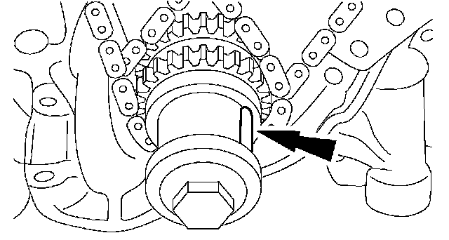
44. Rotate the crankshaft clockwise 120 degrees to the 3 o'clock position to locate the RH camshafts in the neutral position.
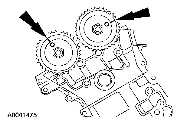
45. Verify that the RH camshafts are correctly positioned.
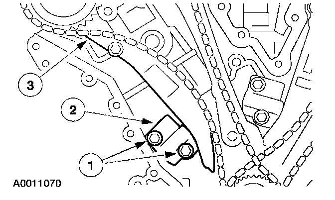
46. Remove the RH timing chain tensioner arm.
1 Remove the bolts.
2 Remove the tensioner.
3 Remove the tensioner arm.
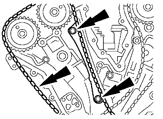
47. Remove the bolts, RH timing chain guide and the timing chain.
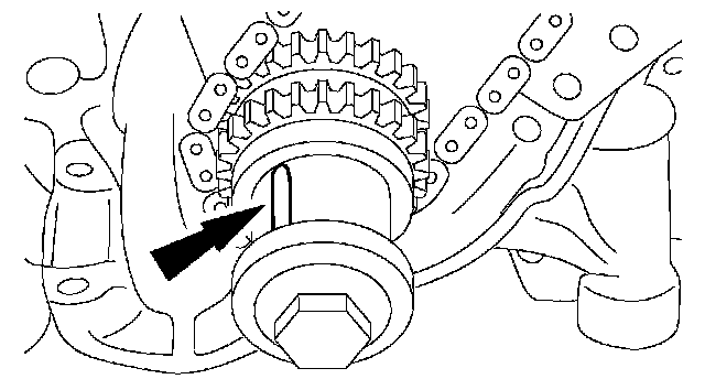
48. Rotate the crankshaft clockwise 600 degrees (1-2/3 times) to position the crankshaft keyway in the 11 o'clock position. This will position the LH camshafts in the neutral position.
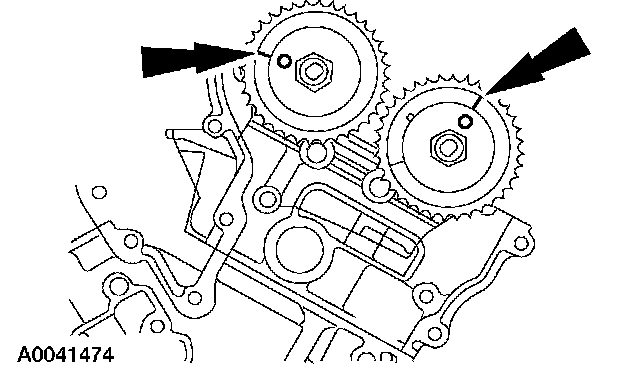
49. Verify that the LH camshafts are in the neutral position.
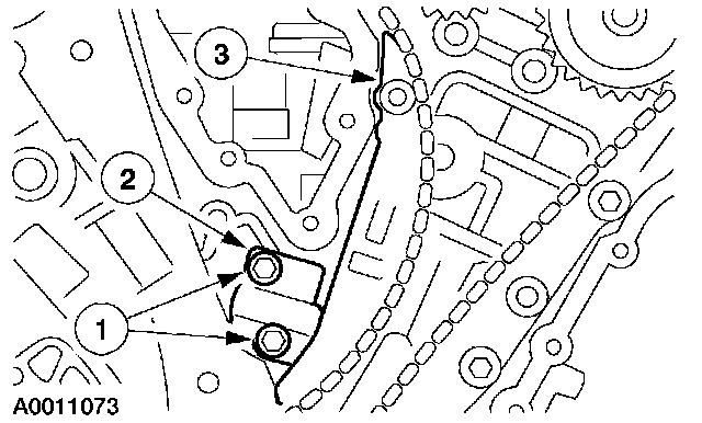
50. Remove the LH timing chain and tensioner arm.
1 Remove the bolts.
2 Remove the tensioner.
3 Remove the tensioner arm.