Steps 61 - 101
61. NOTE: Clean the keyway and slot using metal surface cleaner before applying silicone gasket and sealant.NOTE: The crankshaft damper must be installed and the bolt tightened within four minutes of sealant application.
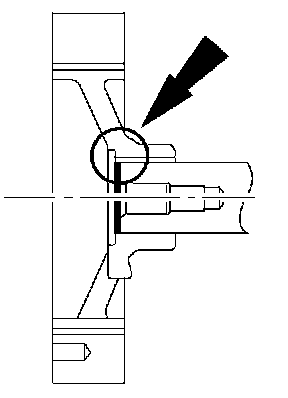
Apply silicone gasket and sealant to the end of the crankshaft damper keyway slot.
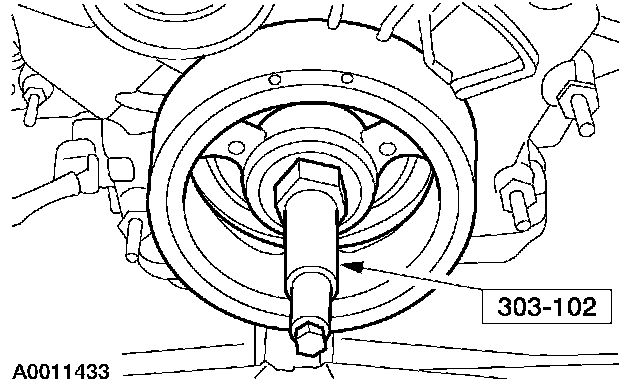
62. Using the special tool, install the crankshaft vibration damper.
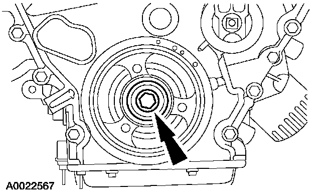
63. Install the crankshaft vibration damper washer and tighten the bolt in four stages.
- Stage 1: Tighten to 120 Nm (89 ft. lbs.).
- Stage 2: Loosen one full turn (360 degrees).
- Stage 3: Tighten to 50 Nm (37 ft. lbs.).
- Stage 4: Tighten to 90 Nm (66 ft. lbs.).
64. Install new gaskets in the valve covers.
65. NOTE: LH shown; RH similar.
NOTE: The valve cover must be installed and the bolts and studs tightened within four minutes of sealant application.
NOTE: Clean cylinder head and front cover surface using metal surface cleaner before applying silicone gasket and sealant.
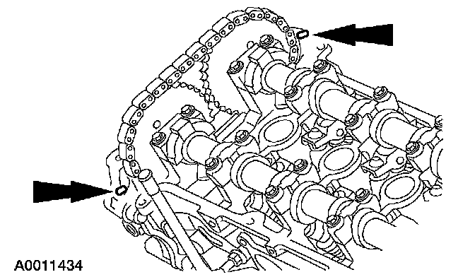
Apply a 8 mm (0.31 inch) dot of silicone gasket and sealant at the cylinder block to front cover mating surface of the LH and RH valve covers.
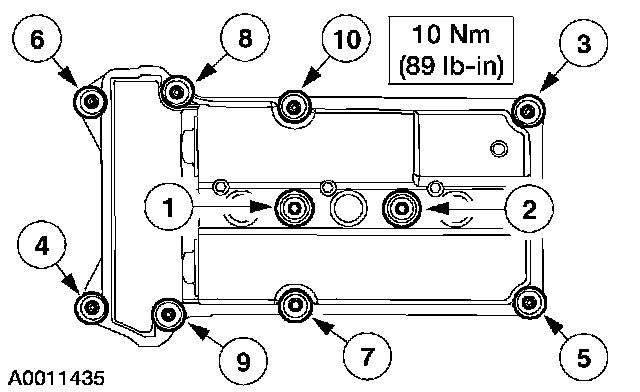
66. Position the RH valve cover and install the bolts and studs in the sequence shown.
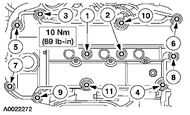
67. Position the LH valve cover and install the bolts and studs in the sequence shown.
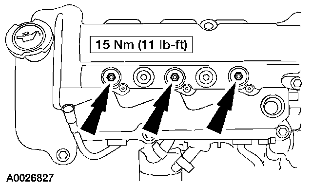
68. Install the spark plugs.
69. NOTE: RH shown; LH similar.
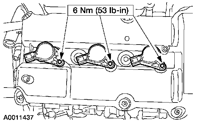
Apply a light film of silicone brake caliper grease and dielectric compound to the interior of the spark plug boot prior to installation.
Install the six coil-on-plugs and install the bolts.
70. Install new gaskets in the lower intake manifold.
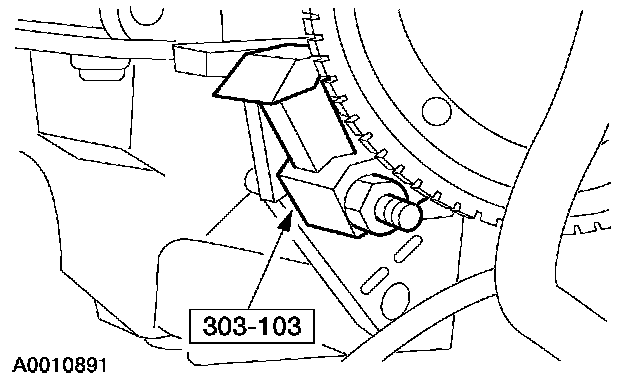
71. Remove the special tool.
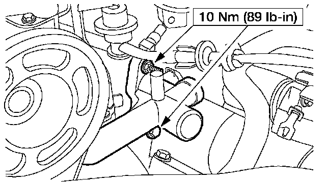
72. Position the coolant bypass tube and connect the hoses.
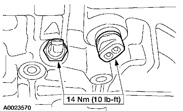
73. Install the oil pressure sender and the block heater.
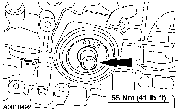
74. Install the oil cooler.
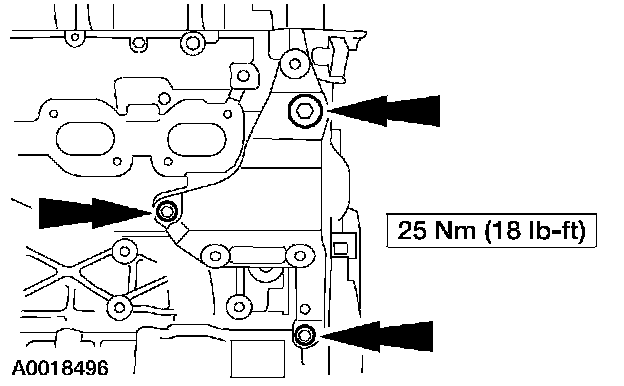
75. Install the generator support bracket.
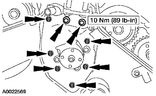
76. Install the power steering pump.
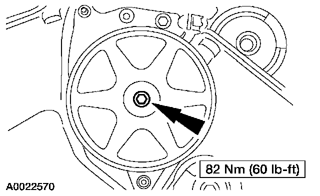
77. Install the power steering pump pulley.
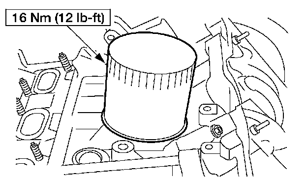
78. Lubricate the O-ring seal and install the oil filter.
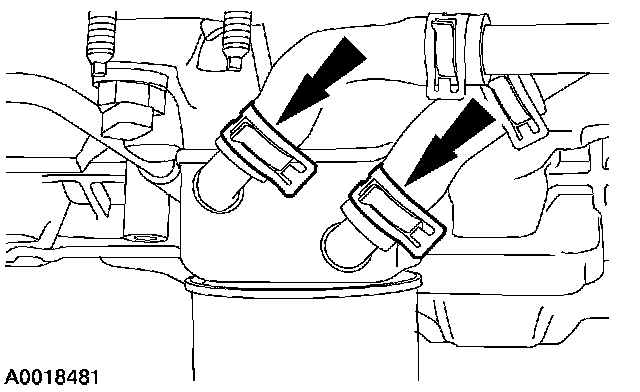
79. Connect the coolant hoses at the oil cooler.
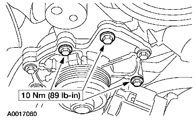
80. Install the water pump assembly.
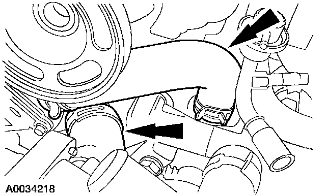
81. Connect the hoses.
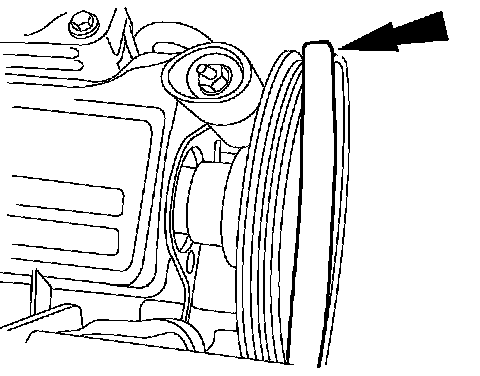
Vehicles not equipped with water pump belt tensioner
82. Install the water pump belt on the water pump pulley and position it on the camshaft pulley.
83. CAUTION: Do not use any screwdrivers, pliers or other metal objects that could cause damage to the belt or camshaft pulley while installing the belt.
Rotate the crankshaft clockwise to seat the water pump belt on the camshaft pulley.
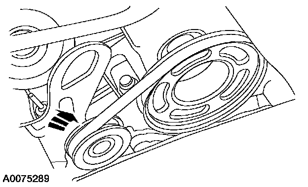
Vehicles equipped with water pump belt tensioner
84. Rotate the drive belt tensioner clockwise and install the water pump belt.
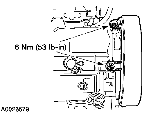
All vehicles
85. Install the water pump belt cover.
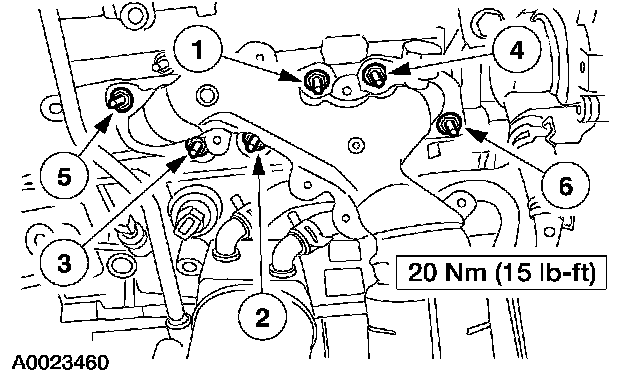
86. Position a new gasket and tighten the exhaust manifold nuts in the sequence shown.
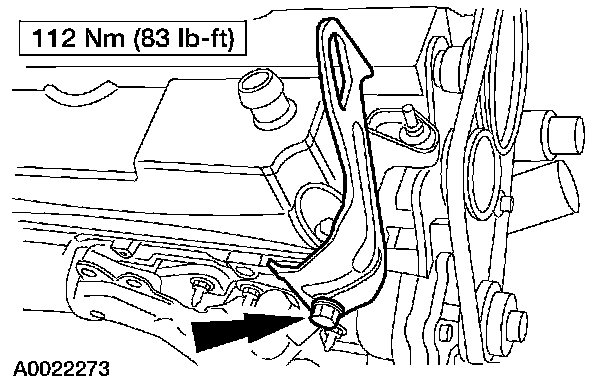
87. Install the engine lift bracket.
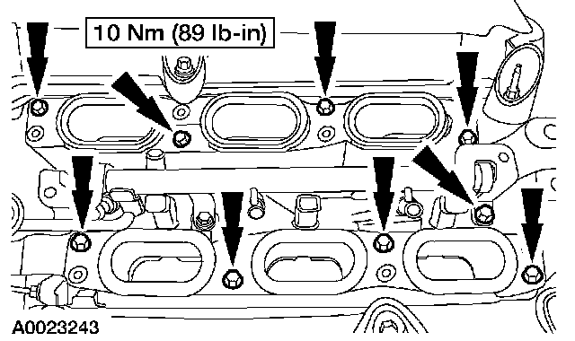
88. Clean the sealing area, position the gasket and install the lower intake manifold.
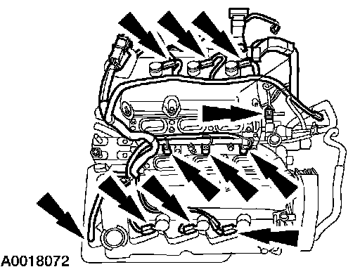
89. Position and connect the engine control sensor wiring in the locations shown.
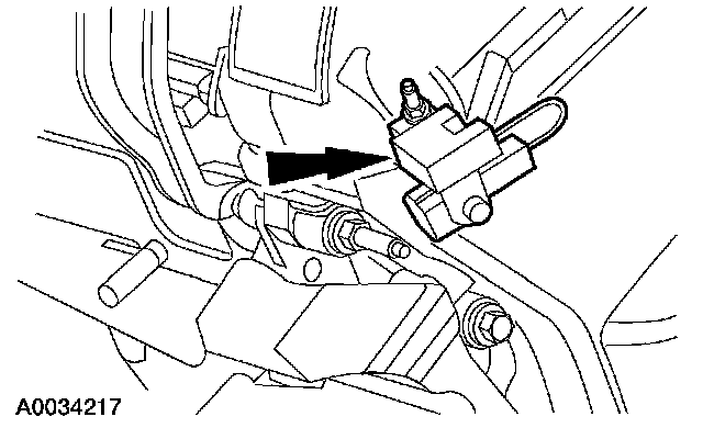
90. Install the radio interference capacitor and the retaining nut.
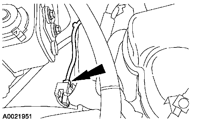
91. Install the radio ignition noise suppressor electrical connector.
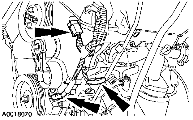
92. Connect the crankshaft and camshaft position sensor electrical connectors.
93. Install new gaskets in the upper intake manifold.
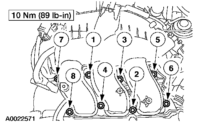
94. Clean the sealing area and install the upper intake manifold.
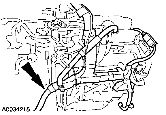
95. Install and connect the engine control wire harness.
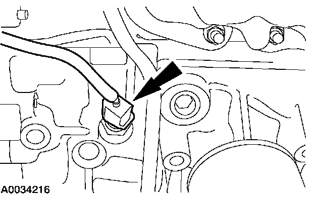
96. Connect the coolant temperature sender and the oil pressure switch.
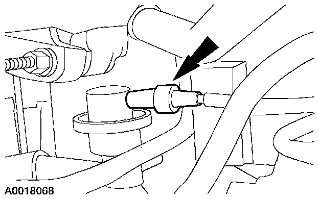
97. Connect the vacuum hose to the fuel pressure damper.
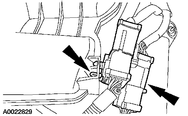
98. Connect the engine control sensor wiring to the upper intake manifold.
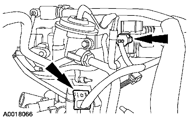
99. Connect the EGR vacuum regulator solenoid and the differential pressure feedback EGR system electrical connectors.
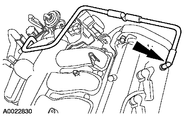
100. Install the PCV tube.
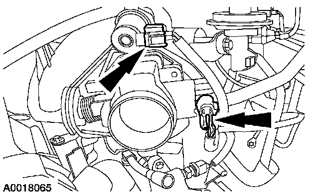
101. Connect the idle air control (IAC) valve and the throttle position (TP) sensor electrical connectors.