Intake Manifold: Service and Repair
Intake Manifold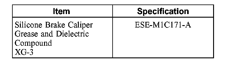
Material
WARNING: Do not smoke or carry lighted tobacco or open flame of any type when working on or near any fuel-related components. Highly flammable mixtures are always present and can be ignited. Failure to follow these instructions can result in personal injury.
1. With the vehicle in neutral, position it on a hoist.
2. Release the fuel system pressure.
3. Disconnect the battery ground cable.
4. Drain the cooling system.
5. Remove the engine air cleaner outlet pipe.
6. Remove the exhaust gas recirculation (EGR) tube.
7. Remove the generator.
8. Disconnect the fuel tube from the fuel injection supply manifold.
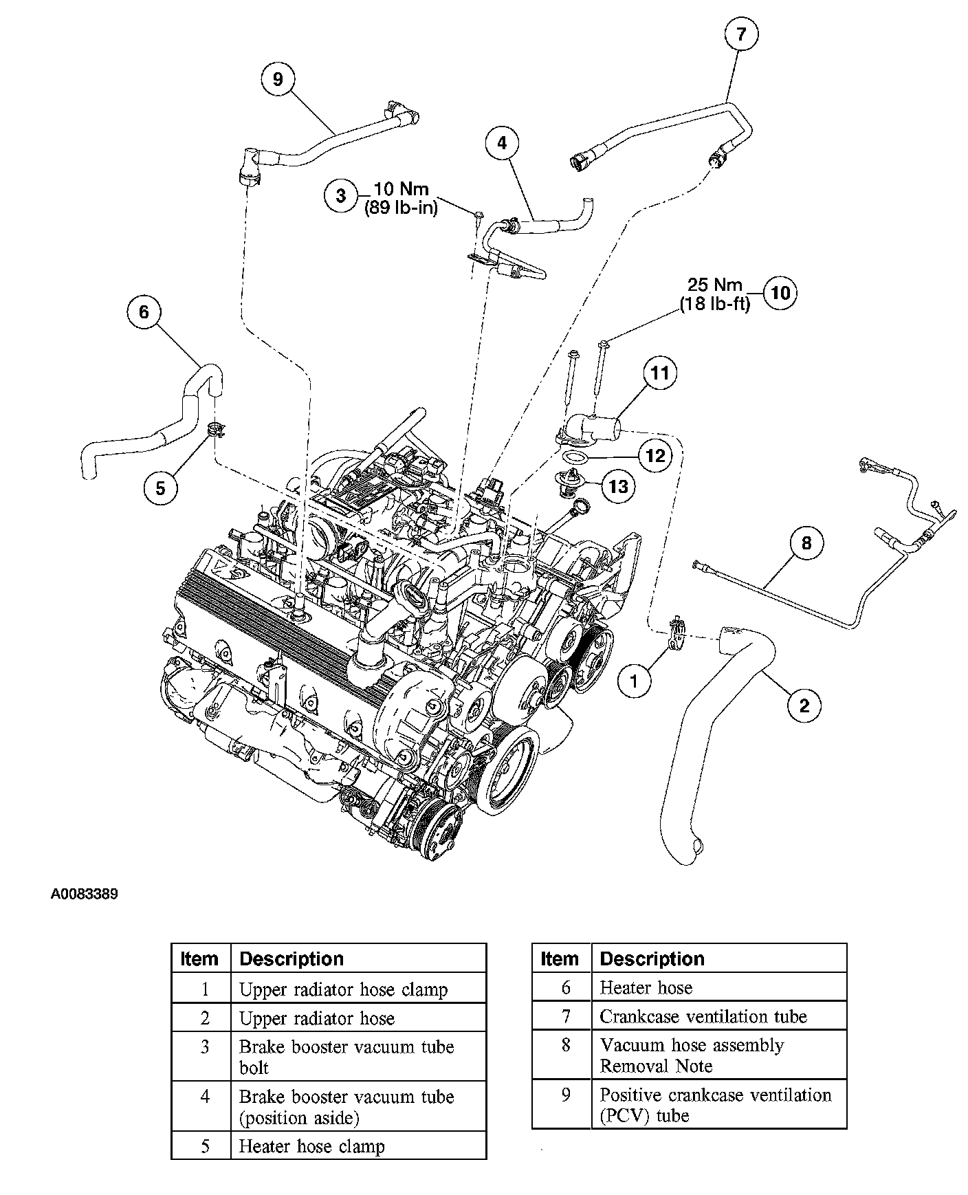
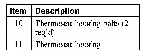
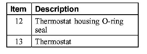
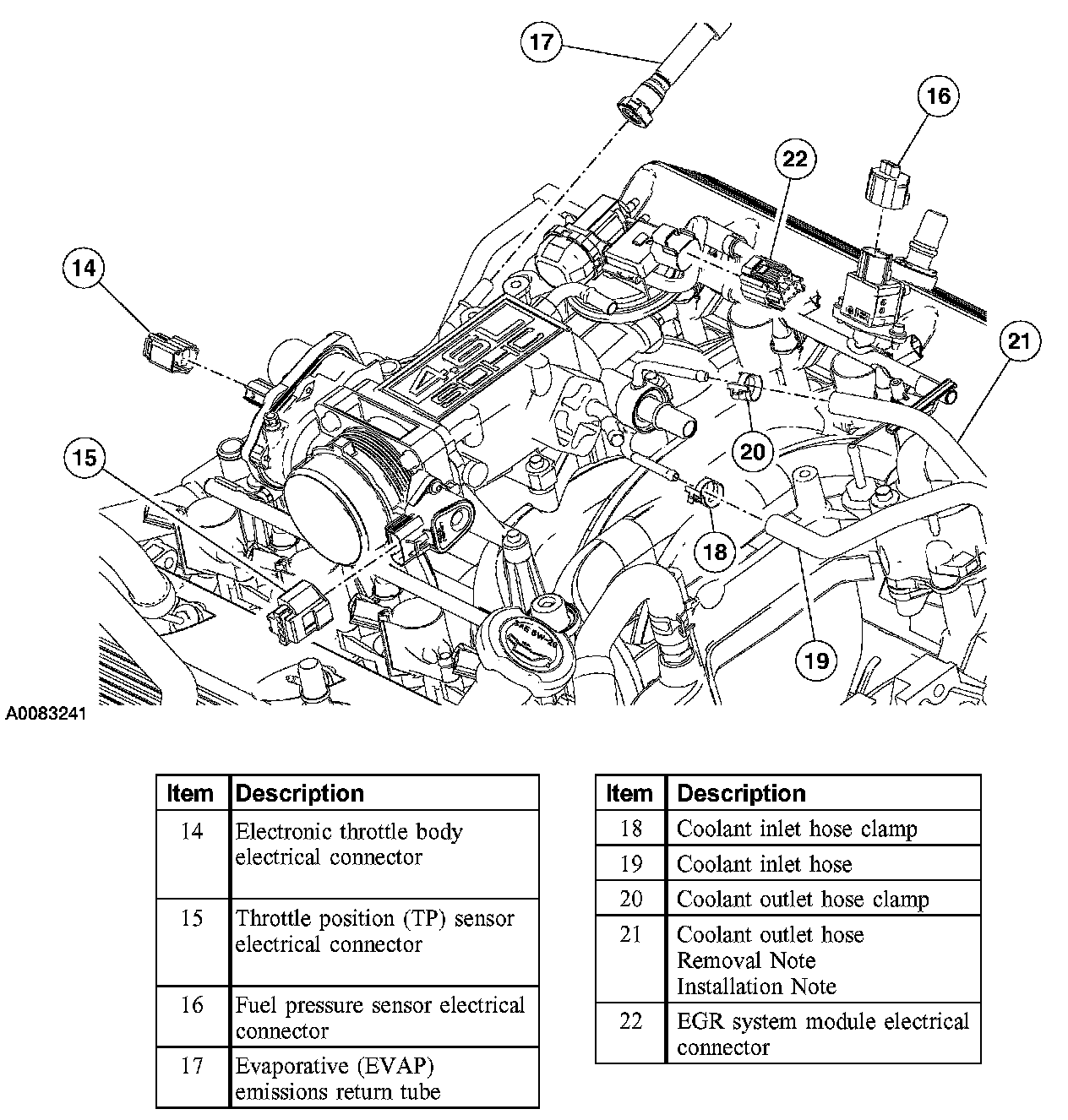
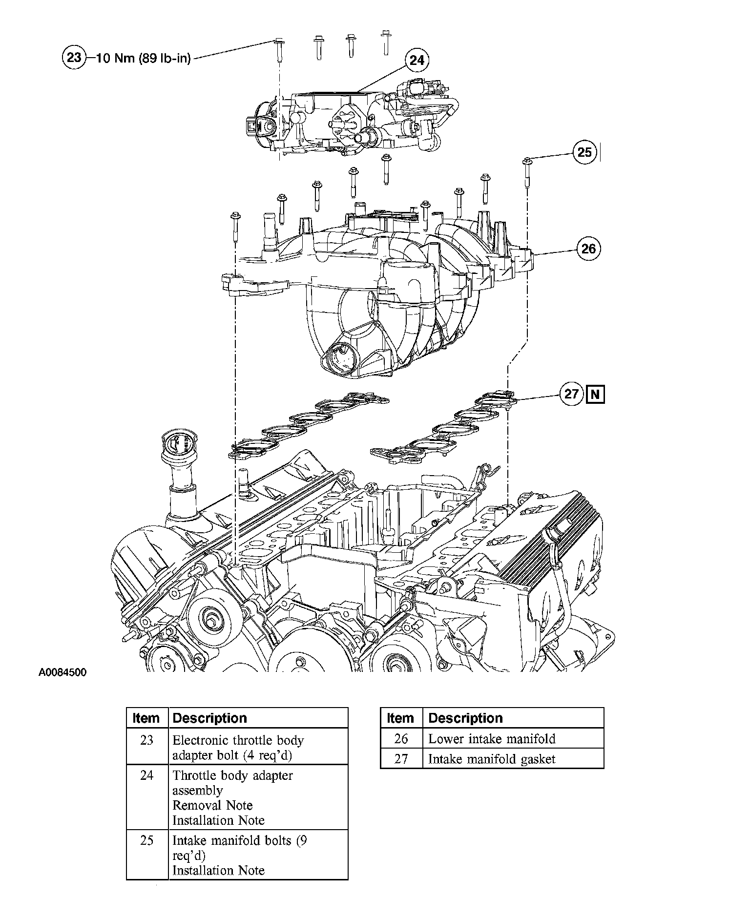
9. Remove the parts in the order indicated in the illustrations and tables.
10. To install, reverse the removal procedure.
11. Fill and bleed the engine cooling system.
Item 8: Vacuum Hose Assembly Removal Note
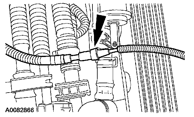
1. Disconnect the heater control vacuum supply hose.
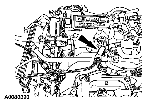
2. Disconnect the vacuum tube from the throttle body adapter.
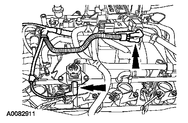
3. Disconnect the EGR system module and fuel pressure sensor vacuum fittings.
^ Remove the vacuum harness from the engine
Item 21: Coolant Outlet Hose Removal Note
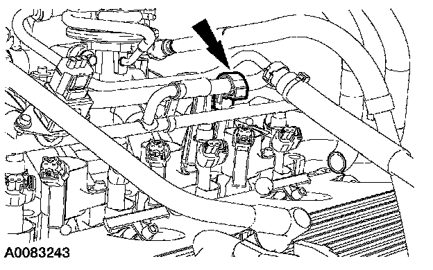
1. Separate the coolant outlet hose anchor from the fuel manifold stud.
Item 24: Throttle Body Adapter Assembly Removal Note
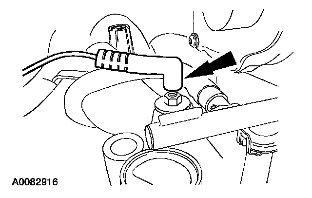
1. Disconnect the ground wire.
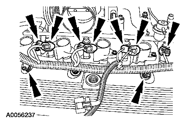
2. Disconnect the RH fuel injector, coil pack electrical connectors and the wiring harness retainers.
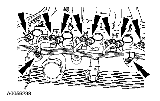
3. Disconnect the LH fuel injector and coil pack electrical connectors and the fuel charging wiring harness retainers.
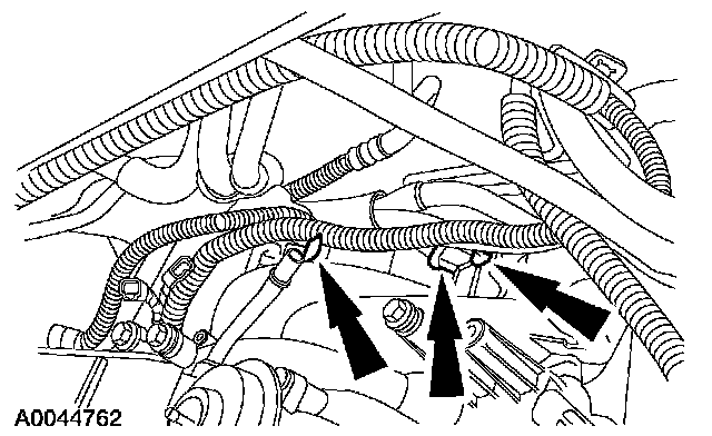
4. Separate the wire harness locators and the knock sensor (KS) electrical connector from the back of the intake manifold.
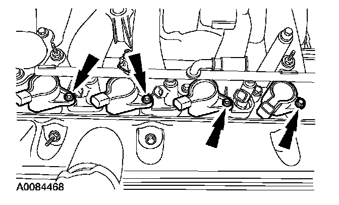
5. NOTE: LH is shown, RH is similar.
Remove the bolts and all eight ignition coils.
Item 25: Intake Manifold Bolts Installation Note

1. Tighten the bolts in the sequence shown.
Item 24: Throttle Body Adapter Assembly
Installation Note
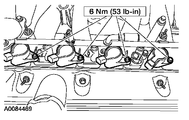
1. NOTE: Apply dielectric compound to the inside of the coil boots.
Install all eight ignition coils.
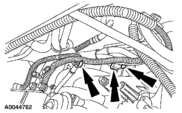
2. Attach the wire harness locators and the KS electrical connector to the back of the intake
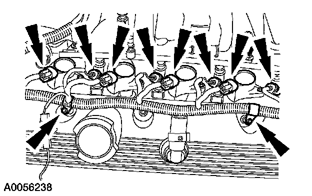
3. Connect the LH fuel injector and coil pack electrical connectors and the fuel charging wiring harness retainers.
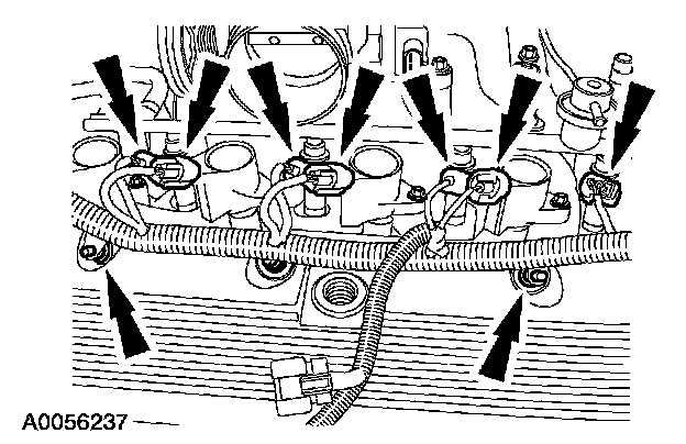
4. Connect the RH fuel injector, coil pack electrical connectors, and the wiring harness retainers.
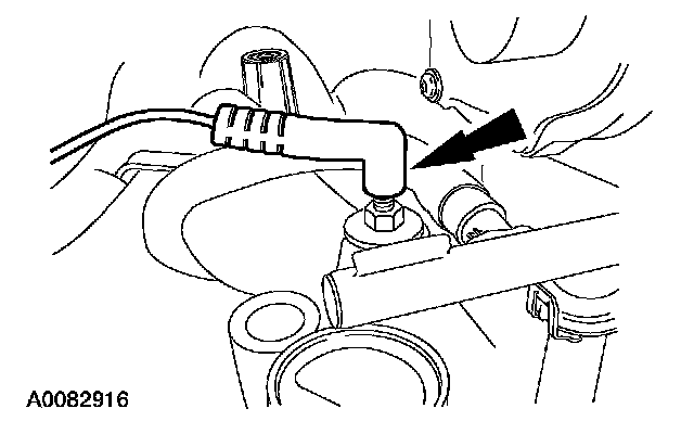
5. Connect the ground wire.
Item 21: Coolant Outlet Hose Installation Note
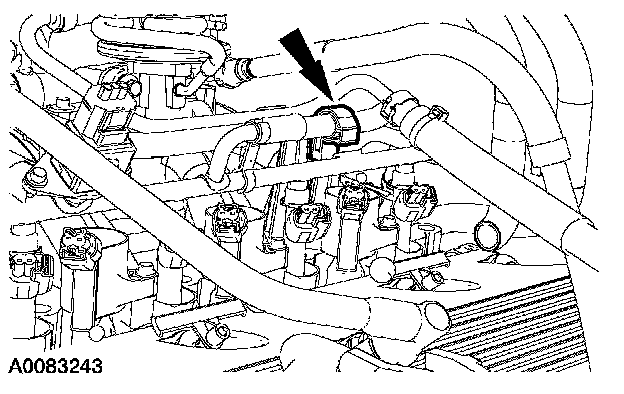
1. Install the coolant outlet hose anchor to the fuel manifold stud.