Engine/Engine Controls - Rough Idle Condition
TSB 05-23-1811/28/05
ROUGH IDLE - 5.4L 3V 4X2 SUPERCAB AND SUPERCREW
FORD:
2004 F-150
This article supersedes TSB 05-19-2 to update the Service Procedure.
ISSUE
Some 2004 F-150 4x2 SuperCab and SuperCrew vehicles equipped with a 5.4L 3-valve engine may exhibit a rough idle, with normal engine operation and no other symptoms.
ACTION
Replace the engine support insulators (engine mounts), neutralize the engine, transmission and exhaust system, then reprogram the powertrain control module to the latest calibration available using WDS release B39.3 or higher. Refer to the following Service Procedure.
SERVICE PROCEDURE
NOTE
READ ENTIRE PROCEDURE BEFORE PROCEEDING. SOME RETAINERS SHOULD NOT BE TIGHTENED UNTIL AFTER THE NEUTRALIZATION PROCEDURE IS COMPLETED.
REMOVAL
1. With the vehicle in Neutral, position it on a hoist. For additional information, refer to Workshop Manual (WSM) Section 100-00.
2. Disconnect the battery ground cable. For additional information, refer to WSM Section 414-00.
3. Remove the throttle body. For additional information, refer to WSM Section 303-04B.
4. Remove the three (3) fluid reservoir bolts and position reservoir aside.
5. Rotate the belt tensioner clockwise and detach the drive belt from the generator pulley.
6. Remove the upper radiator sight shield.
7. Remove the bolts and position the cooling fan shroud away from the radiator.
8. Remove the bolts and the generator support bracket.
9. Remove the bolts and position the generator aside.
10. Install Special Tool 303-F073 (3 Bar Engine Support).
11. Remove the four (4) exhaust manifold to catalytic converter nuts.
12. Remove the exhaust system support bracket bolts from the cross member.
13. Loosen the transmission mount nuts.
14. Remove the starter. For additional information, refer to WSM Section 303-04B.
15. Remove the oil level indicator and tube. Refer to WSM Section 303-01B.
16. Remove the right hand (RH) engine support insulator nuts and washer.
17. Remove the left hand (LH) engine support insulator bolt.
18. Raise the engine.
19. Remove the three (3) RH engine support insulator bracket bolts.
20. Remove the RH engine support insulator assembly.
21. Remove the three (3) LH engine support insulator bracket bolts.
22. Remove the LH engine support insulator assembly.
INSTALLATION AND NEUTRALIZATION
1. Install the LH engine support insulator bracket assembly.
2. Install the three (3) LH engine support insulator bracket bolts. Tighten to 46 lb-ft (62 N.m).
3. Install the RH engine support insulator bracket assembly.
4. Install the three (3) RH engine support insulator bracket bolts. Tighten to 46 lb-ft (63 N.m).
5. Lower engine.
6. Install the LH engine support insulator through bolt. (Do not tighten until after neutralization procedure)
CAUTION
ONLY USE HAND TOOLS WHEN INSTALLING THE LH ENGINE MOUNT BOLT OR DAMAGE TO THE ENGINE MOUNT CAN OCCUR.
NOTE
EARLY BUILT VEHICLES ARE EQUIPPED WITH AN M14 THROUGH BOLT. LATE BUILD VEHICLES ARE EQUIPPED WITH AN M18 THROUGH BOLT. IF THE M14 THROUGH BOLT ENGINE SUPPORT INSULATOR NUT IS MISSING OR DAMAGED, INSTALL A NEW NUT USING SERVICE PART NUMBER W709375. IF THE M14 THROUGH BOLT ENGINE SUPPORT INSULATOR NUT CAGE IS DAMAGED OR MISSING, INSTALL A NEW NUT USING SERVICE PART NUMBER W520516-5301.
7. Install RH engine support insulator nuts and washer. (Do not tighten until after neutralization procedure)
CAUTION
ONLY USE HAND TOOLS WHEN INSTALLING THE RH ENGINE MOUNTS NUTS OR DAMAGE TO THE ENGINE MOUNTS CAN OCCUR.
8. Install the oil level indicator and tube. Refer to WSM Section 303-01B.
9. Install the starter. For additional information, refer to WSM Section 303-04B.
10. Install the exhaust system support bracket bolts to the crossmember. (Do not tighten until after neutralization procedure)
11. Install the four (4) exhaust manifold to catalytic converter nuts. (Do not tighten until after neutralization procedure)
12. Loosen all exhaust slip coupling back to muffler.
13. Lower the vehicle to the ground.
14. Remove the engine support tool (303-F073 Three Bar Support).
15. Position generator and install retainers. Tighten to 18 lb-ft (24 N.m).
16. Install the generator support bracket. Tighten to 89 lb-in (10 N.m).
17. Position the cooling fan shroud and install the bolts. Tighten to 89 lb-in (10 N.m).
18. Reinstall the upper radiator sight shield.
19. Rotate the belt tensioner clockwise and install the drive belt onto the generator pulley.
20. Position the fluid reservoir and install the three (3) fluid reservoir bolts. Tighten to 8 lb-ft (11 N.m).
21. Install the throttle body. For additional information, refer to WSM Section 303-04B.
22. Connect the battery ground cable. For additional information, refer to WSM Section 414-00.
NOTE
THE FOLLOWING NEUTRALIZATION PROCEDURE SHOULD BE PERFORMED ON A DRIVELINE/DRIVE-ON HOIST, IF AVAILABLE, SO THE VEHICLE IS SUPPORTED BY THE WHEELS.
23. Apply parking brake, apply service brake, start engine, then perform the following while keeping the brakes applied.
24. Shift the transmission in Drive and give a short quick tap on the accelerator pedal to raise engine RPM to 1600-2000 RPM, return vehicle to idle.
25. Shift the transmission to Reverse and give a short quick tap on the accelerator pedal to raise engine RPM to 1600-2000, return to idle. Repeat Drive and Reverse procedure a second time.
26. Shift the transmission to Neutral and raise engine RPM one time to 3000 RPM, turn off engine and shift transmission into Park.
27. Raise the vehicle back up on the hoist.
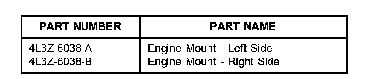
28. Tighten and torque the neutralized components in the following order:
a. Through bolt on left hand mount to 162 lb.ft (220 N.m).
b. Nuts on the right hand mount (Larger M14 to 155 lb-ft (210 N.m), then smaller M8 to 18 lb-ft (24 N.m)).
c. Transmission mount to 76 lb4t (103 N.m).
CAUTION
DO NOT SUPPORT THE EXHAUST SYSTEM ON STANDS DURING THE FOLLOWING STEPS
d. LH exhaust manifold coupling then RH exhaust manifold coupling to 30 lb-ft (41 N.m).
e. Y-pipe exhaust isolator at the transmission cross member to 15 lb-ft (20 N.m).
f. Slip coupling between the Y-pipe and the muffler pipe to 35 lb-ft (48 N.m).
29. Visually inspect the exhaust hangers to verify the isolators are centered.
30. Reprogram the PCM to the latest calibration using WDS release B39.3 or higher. Calibration files may also be obtained at the website.
WARRANTY STATUS: Eligible Under Provisions Of New Vehicle Limited Warranty Coverage
OPERATION DESCRIPTION TIME
052318A F-150 5.4L 4X2 Super 3.0 Hrs.
Cab, Crew Cab: Replace
The Engine Support
Isolators, Neutralize The
Engine, Transmission, And
Exhaust System, Then
Reprogram The Powertrain
Control Module (Do Not
Use With 12650D,
12650D84, 6038A, 5200A,
3697A, 9926A)
DEALER CODING
CONDITION
BASIC PART NO. CODE
6038 42
OASIS CODES: 499000, 608000, 608400, 703000, 703100

Disclaimer