Test I
PINPOINT TEST I: NO CONTROLLER AREA NETWORK (CAN) COMMUNICATIONTest I1-I3:
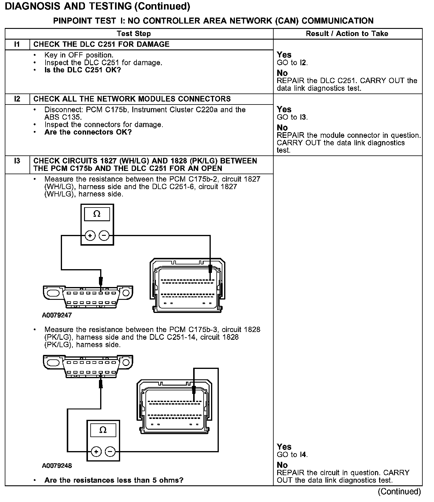
Test I4-I6:
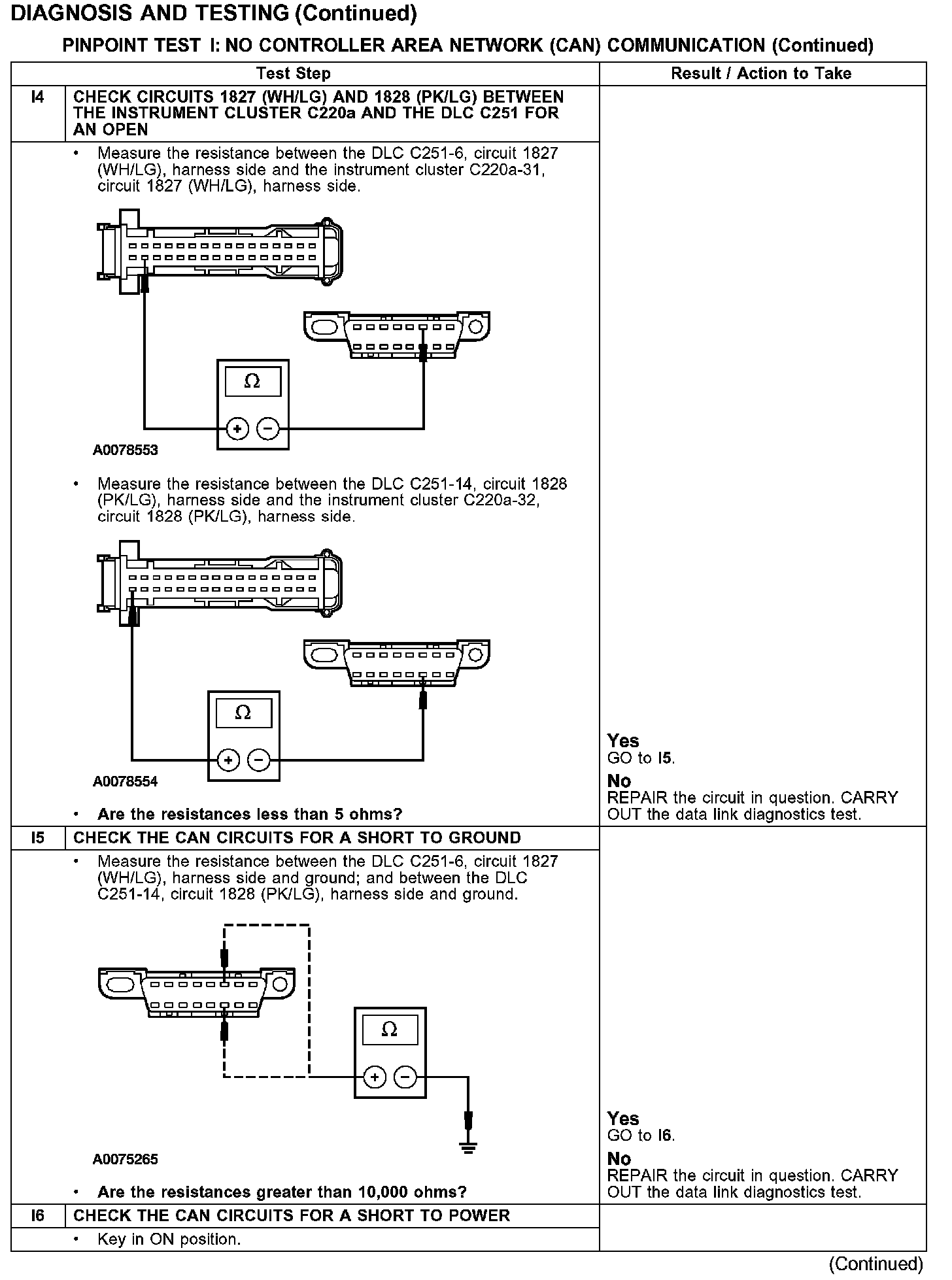
Test I6-I10:
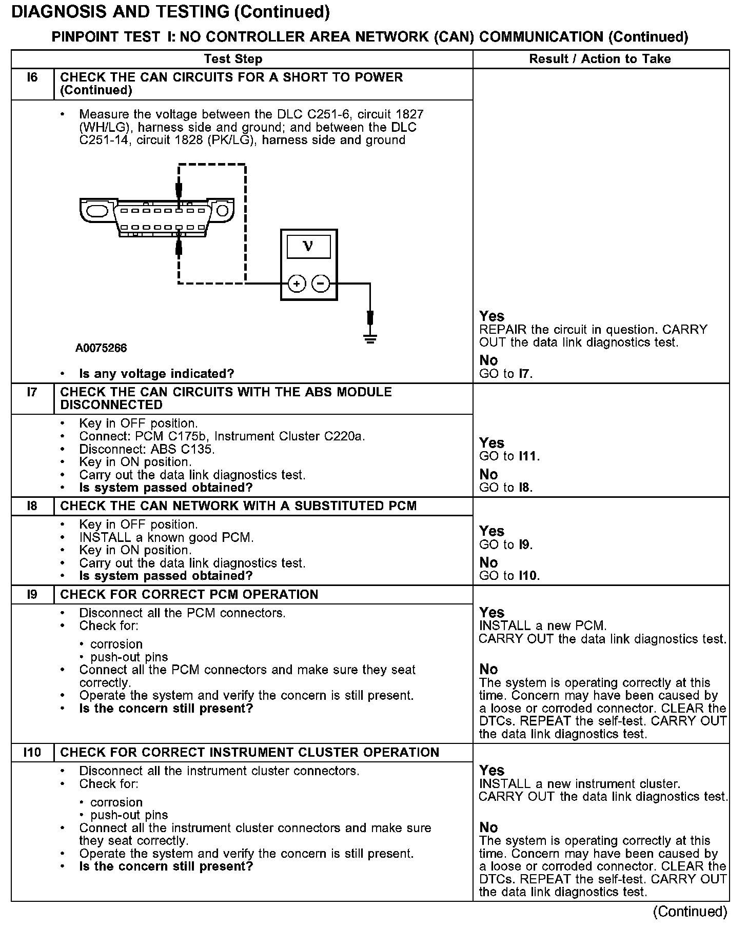
Test I11:
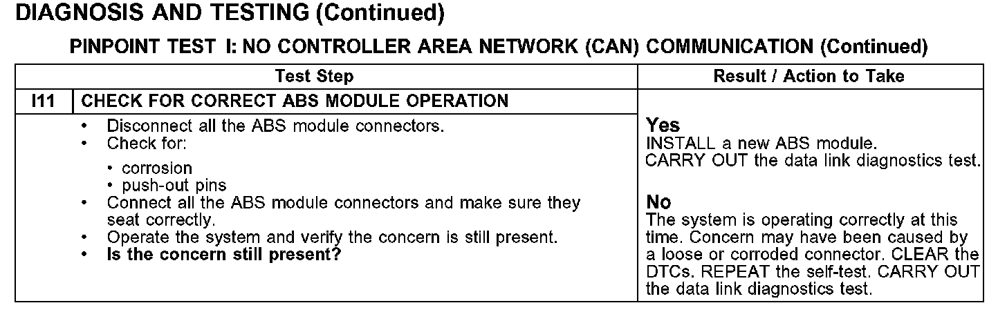
Normal Operation
The PCM, ABS module and the instrument cluster communicate with the diagnostic tool through CAN circuits 1827 (WH/LG) and 1828 (PK/LG). If one of the bus wires become shorted to ground or voltage, or if some but not all termination resistors are lost, communications can continue. If a module is lost due to internal concerns, communications can continue to all other modules. Check circuits 1827 (WH/LG) and 1828 (PK/LG) between the PCM C175b, ABS module C135, instrument cluster C220a, and the DLC C251. Total resistance values must not be more than 5 ohms. If the resistance is more than 5 ohms there is an open in circuits 1827 (WH/LG) and 1828 (PK/LG), damage to the DLC C251, damage to the PCM C175b, ABS module C135, instrument cluster C220a, a problem in the in-line connectors or an internal problem with the PCM, ABS module, or the instrument cluster. If, after individual checks of each circuit leading to a module show resistance values less than 5 ohms and no in-line connector issues present, the data link diagnostics test must be run with the module in question disconnected. If the data links diagnostics test passes with the module in question disconnected, it is the source of the concern and should be removed and a new module installed.
Possible Causes
- CAN circuits 1827 (WH/LG) and 1828 (PK/LG) shorted to ground or open
- CAN circuits 1827 (WH/LG) and 1828 (PK/LG) shorted to power
- in-line connector
- DLC C251
- PCM C175b
- ABS module C135
- instrument cluster C220a
- PCM
- ABS module
- instrument cluster