Introduction To Ford Diagrams
Introduction
Note: All wiring connections between components are shown exactly as they exist in the vehicles. It is important to realize, however, that no attempt has been made on the schematics to represent components and wiring as they physically appear on the vehicle. For example, a 4-foot length of wire is treated no differently in a schematic from one that is only a few inches long. Furthermore, to aid in understanding electrical (electronic) operation, wiring inside complicated components has been simplified.
Complete Circuit
Each circuit is show completely and independently in one cell. Other components that are connected to the circuits may not be shown unless they influence the circuit operation.
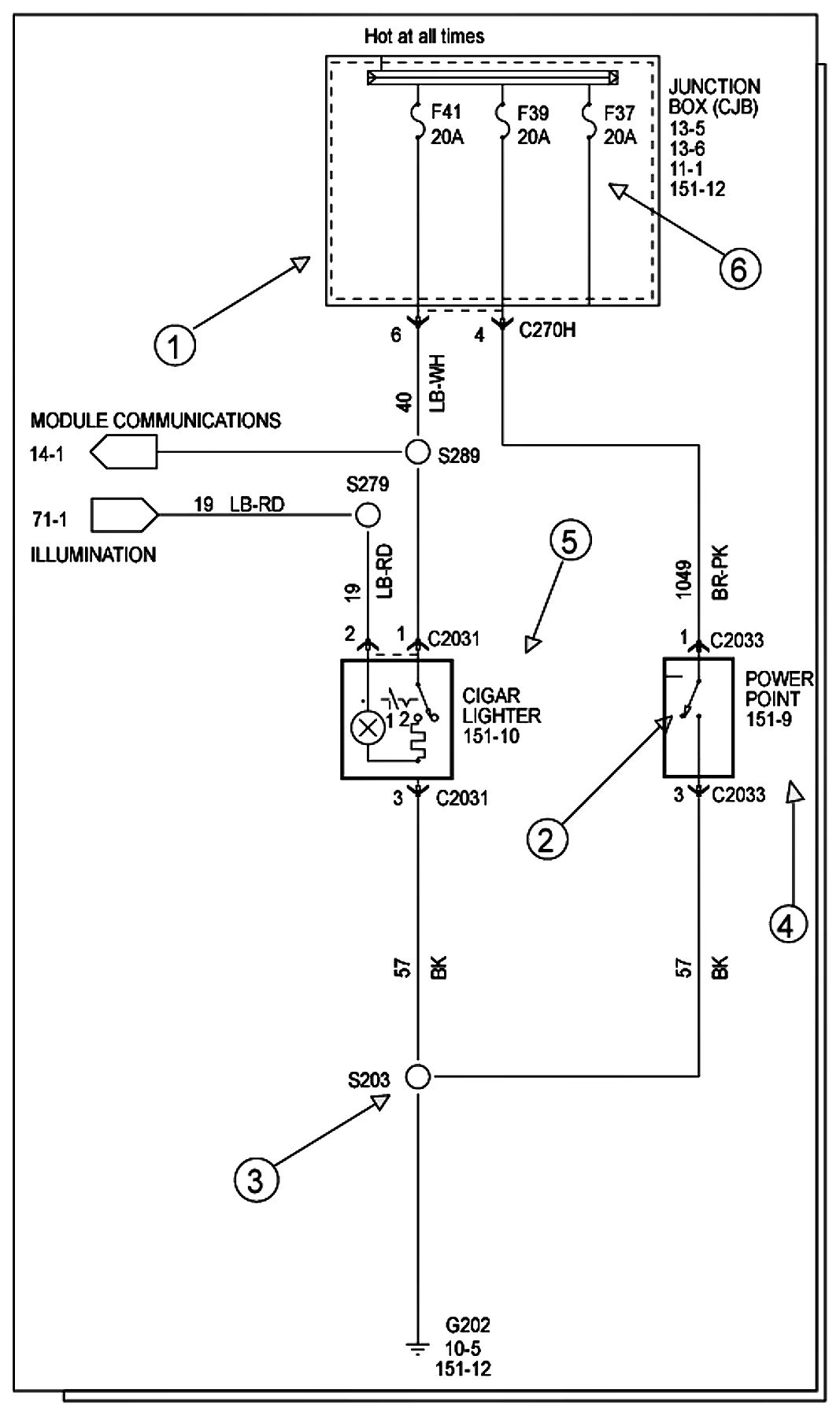
Current Flow (1)
Each cell normally starts with the component that powers the circuit, such as a fuse or the ignition switch. Current flow is shown from the power source at the top of the page to ground at the bottom of the page. A full representation of the power supply of a fuse or the power distribution from a fuse to various components is given in cell 13 "Power Distribution". Full representation of the ground connections are show in cell 10 "Grounds".
Switch Positions (2)
Within a schematic, all switches, sensors and relays are shown "at rest" (as if the ignition switch were OFF).
Splices (3)
Splices directly connecting to the power distribution are best represented on the power distribution schematic in cell 13 "Power Distribution". Splices connected to grounds can be seen completely in cell 10 "Grounds". For all other splices, a reference is given to each off page where that particular splice can be best viewed.
Component Referencing (4)
The Power Distribution components are ground components on a schematic have a reference to component location view or the page where it is show completely. All other components have a reference to a component location view only. It is located to the right of each component.
Component Names (5)
Component names are placed on the right hand side of each component when possible. Descriptions of the internals of the component are also included when available. The page where the component appears in full is listed in the Index.
Internal Name and Function Identification Numbers (6)
Some components on each page have internal symbols with an identification number located within it. You can identify the internal symbol or function by finding the corresponding number under the component name.
Fuse and Relay Information
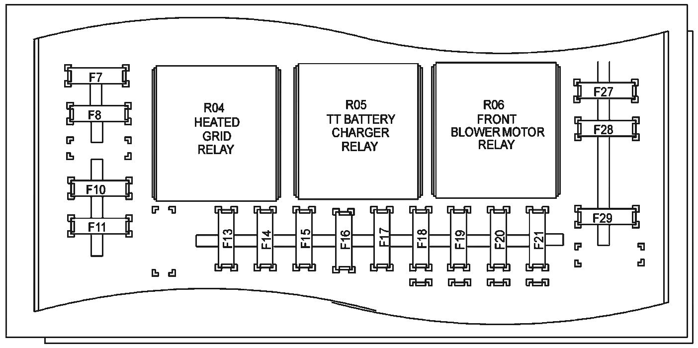
Fuse and Relay Information contains a view of the fuse/relay box in which all fuses and relays are identified. Fuse and Relay numbering and naming. Fuse and relay numbering and naming follow the indication of the fuse panel cover.
Power Distribution
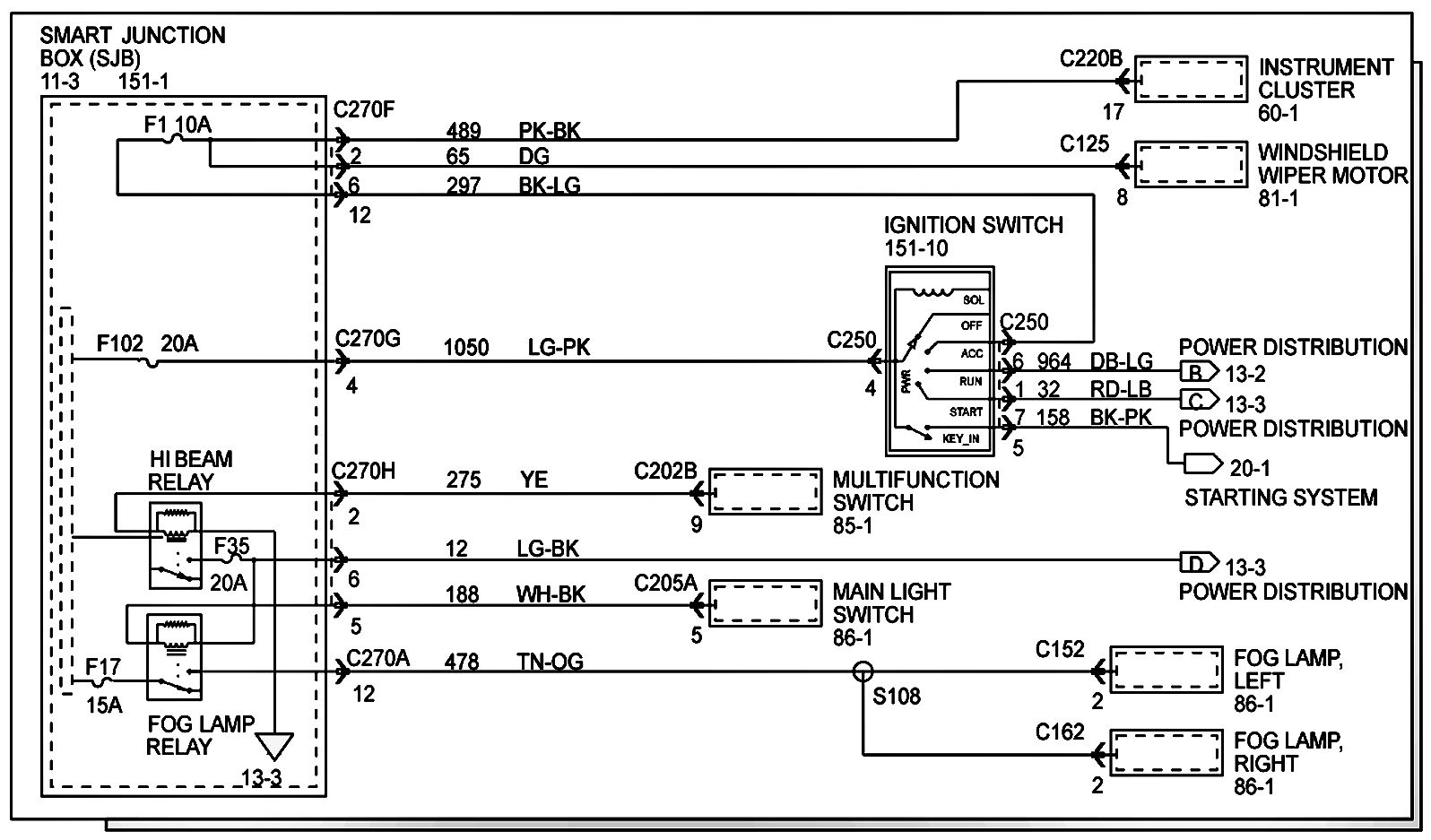
Power Distribution shows the current feed circuits. The current path is shown from the battery to the ignition switch and to all fuses. It also shows the circuits protected by each fuse. The circuit is traces from the fuse to the component. All details (wires, splices, connectors) between the fuse and the first component are shown.
Ground Distribution
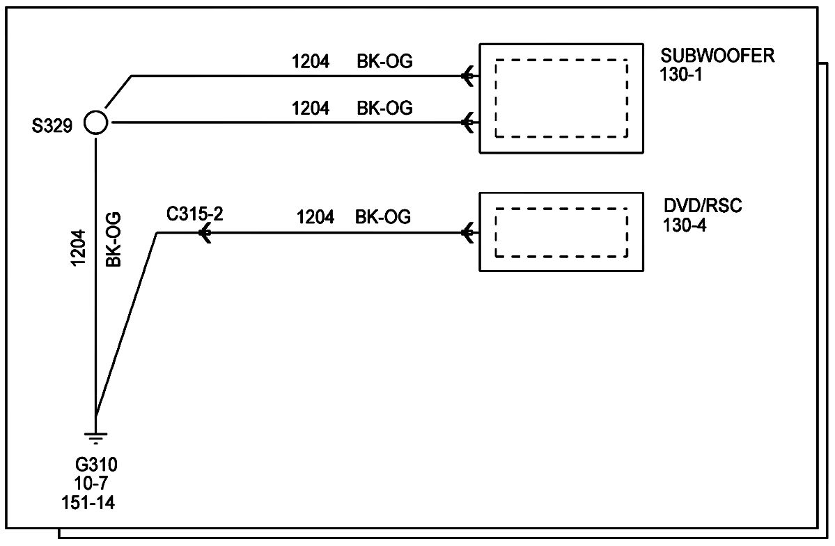
Grounds contains the schematic that shows the complete details for each ground connection or main ground splice. There is also a description of the ground location of the vehicle and the harness it resides on. This is useful is diagnosing a problem affecting several components at once (poor ground connection or ground splice). All details (wires, splices, connectors) between the ground point and the component are shown. These ground connection details are shown here in order to keep the individual cell schematics as uncluttered as possible.
Component and Connector Information
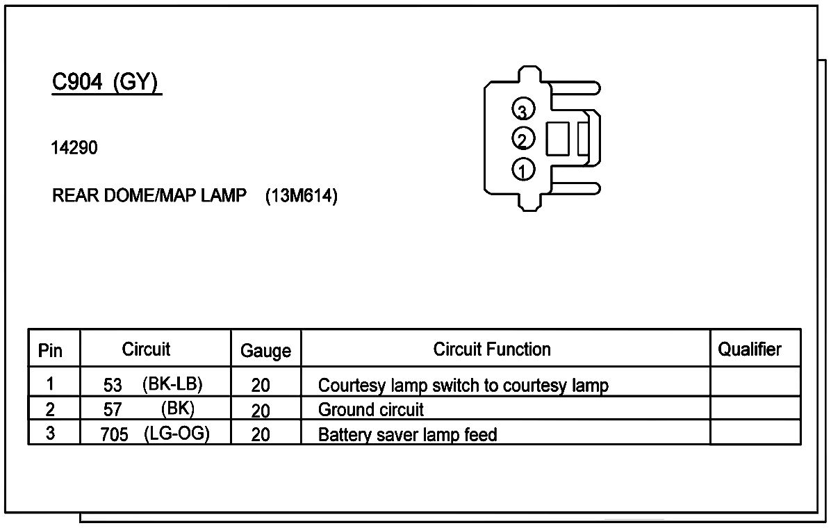
Component location charts helps the user find where the various items depicted on the schematic can physically be found on the vehicle. A brief written description of the location is given, along with a reference to the component location views.
Component location views show the components and their connection wires as they can be found the vehicle.
Component views show the views of the pins and/or cavities of all connectors. The pin and cavity sides are shown separately as if the connector were disconnected. The color of the connector housing is indicated next to the connector number when available. The harness casual number is located above the connector view and below the connector. The wiring harness designations are listen in Component Location Chart.
Warnings:
- Always wear safety glasses for eye protection.
- Use safety stands whenever a procedure requires being under a vehicle.
- Be sure the IGNITION SWITCH is always in the OFF position, unless otherwise required by the procedure.
- Set the parking brake when working any vehicle. An automatic transmission should be in PARK. A manual transmission should be in NEUTRAL.
- Operate the engine only in well-ventilated area to avoid danger of carbon monoxide.
- Keep away from moving parts, especially the fan and belts, when the engine is running.
- To prevent serious burns, avoid contact with hot metal parts such as the radiator, exhaust manifold, tail pipe, catalytic converter and muffler.
- Do not allow flame or sparks near the battery. Gases are always present in and around the battery cell. An explosion could occur.
- Do not smoke when working on a vehicle.
- To avoid serious injury, always remove rings, watches, loose hanging jewelry and avoid wearing lose clothing.
- The vehicle is equipped with high voltage cables, components, and wiring. The high voltage warning labels containing the high voltage symbol are located on each high voltage component. High voltage cables, and wiring are orange in color. Certified rubber insulation gloves and a face shield must be worn when working with the high voltage cables, components, or wiring. The ignition key must be cycled to the off position for a minimum of 5 minutes, and the high voltage traction battery service disconnect plugs placed in the servicing/shipping position before disconnecting the high voltage cables. Failure to follow these instructions may result in personal injury or death.
- Do not disconnect, disable, or touch the high voltage cables, components, or wiring during the module reprogramming procedure because high voltage is present. The high voltage warning labels containing the high voltage symbol are located on each high voltage component. High voltage cables, and wiring are orange in color. Failure to follow these instructions may result in personal injury or death.
- The normal high voltage traction batter coltage is 330 volts DC. The buffer zone must be set up and high voltage insulated safety gloves and a face shield must be worn. Failure to follow these instructions may result in personal injury or death.
- The high voltage traction battery and charging system contains high voltage components and wiring. High voltage insulated safety gloves and a face shield must be worn when carrying out any diagnostics on this vehicle. Failure to follow these instructions may result in personal injury or death.
- Before carrying out an removal and installation procedures of the high voltage traction battery system, the high voltage traction battery must be depowered. Failure to follow these instructions may result in personal injury or death.
- The high voltage insulated safety gloves are to be worn while working on the high voltage system should be of the appropriate safety and protection rating for use on the high voltage system. They must be inspected before use and must always be worn in conjuction with the leather outer glove. Any hole in the rubber insulating glove is a potential entry point for high voltage. Failure to follow these instructions may result in personal injury or death.
- High voltage insulated safety gloves and a face shield must be worn when working with high voltage cables. The ignition switch must be OFF for a minimum of 5 minutes before removing high voltage cables. Failure to follow these instructions may result in personal injury or death.
- The buffer zone is required when working with the high boltage system. Failure to follow these instructions may result in personal injury or death.