Shift Interlock Solenoid: Service and Repair
Brake Shift Interlock ActuatorRemoval and Installation
1. WARNING: To avoid accidental deployment and Possible personal injury, the backup power supply must be depleted before repairing or replacing any front or side air bag supplemental restraint system (SRS) components and before servicing, replacing, adjusting or striking components near the front or side air bag sensors, such as doors, instrument panel, console, door latches, strikers, seats and hood latches.
The side air bag sensors are located at or near the base of the B-pillar.
To deplete the backup power supply energy, disconnect the battery ground cable and wait at least one minute. Be sure to disconnect auxiliary batteries and power supplies (if equipped).
Disconnect the battery ground cable. Wait at least one minute before proceeding with the procedure to allow the backup power supply to deplete its energy.
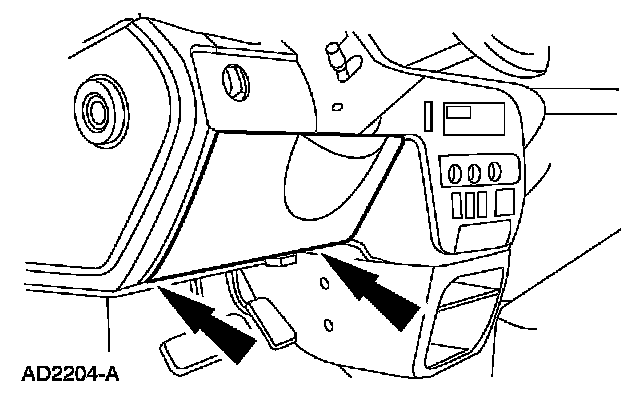
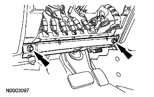
2. Remove the 2 screws and the instrument panel lower steering column opening cover.
^ To install, tighten to 12 Nm (9 ft. lbs.).
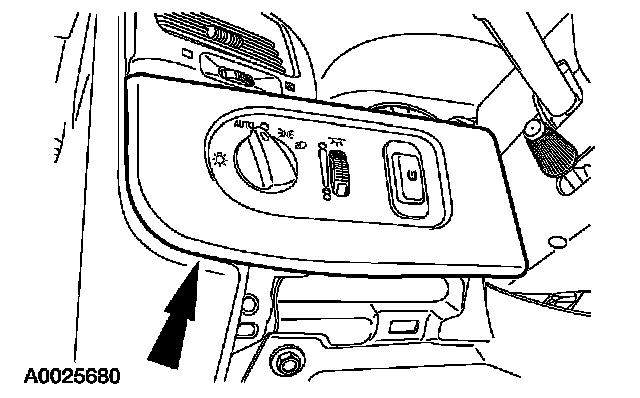
3. Separate the LH instrument panel finish panel from the instrument panel.
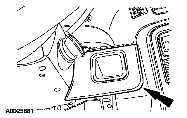
4. Remove the RH instrument panel finish panel.
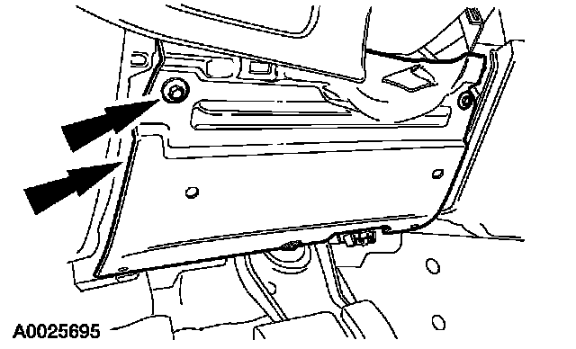
5. Remove the screws and the instrument panel opening cover reinforcement.
^ To install, tighten to 12 Nm (9 ft. lbs.).
6. Remove the screws and the steering column opening brace.
^ To install, tighten to 15 Nm (11 ft. lbs.).
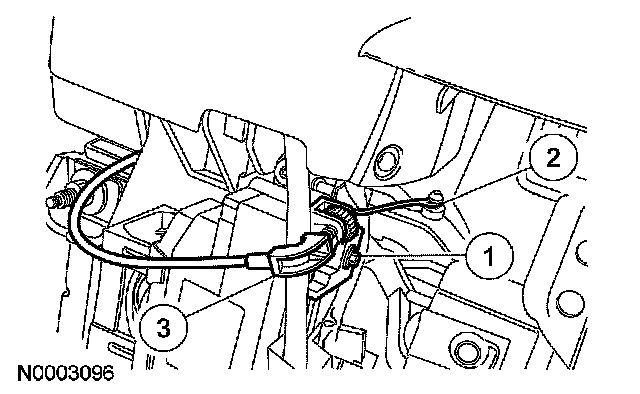
7. Position the selector lever indicator cable aside.
1. Loosen the screw.
^ To install, tighten to 4 Nm (35 inch lbs.).
2. Disconnect the cable.
3. Position the selector lever indicator cable aside.
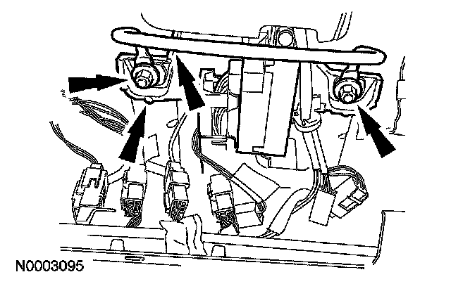
8. Remove the 4 nuts and the bracket, and lower the steering column.
^ To install tighten to 15 Nm (11 ft. lbs.).
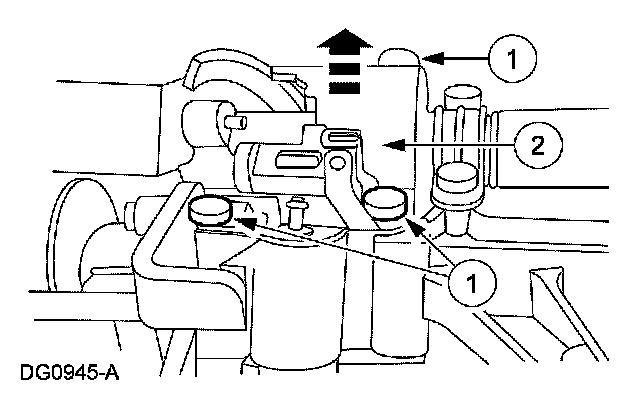
9. Remove the brake shift interlock actuator and the transmission shift selector position insert.
1. Remove the 3 bolts.
^ To install, tighten to 9 Nm (80 inch lbs.).
2. Remove the brake shift interlock actuator and the transmission shift position insert.
10. To install, reverse the removal procedure.