Part 2
EngineAssembly (Steps 33-65)
33. Install the 10 bolts.
^ Tighten to 25 Nm (18 ft. lbs.).
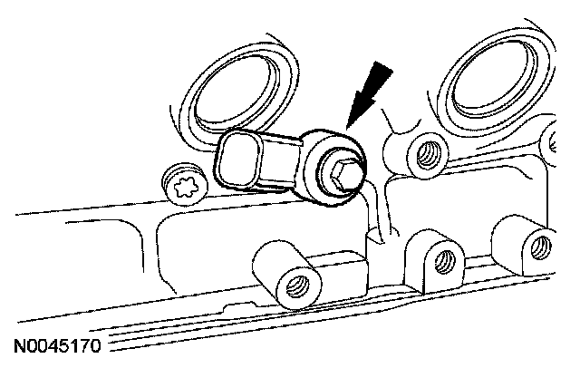
34. Install the knock sensor (KS) and bolt.
^ Tighten to 25 Nm (18 ft. lbs.).
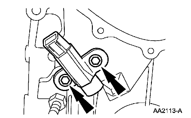
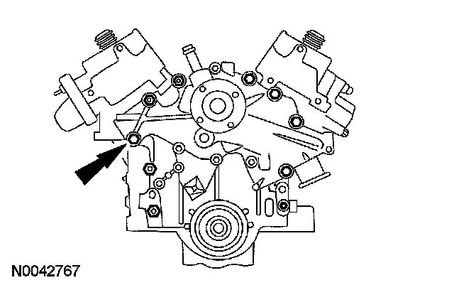
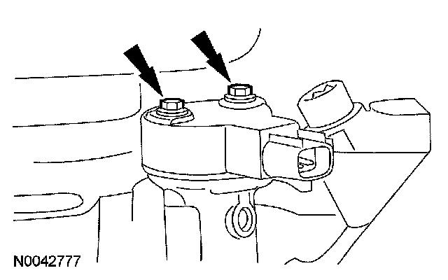
35. Install the crankshaft position (CKP) sensor and bolts.
^ Tighten to 10 Nm (89 inch lbs.).
36. CAUTION: Do not use metal scrapers, wire brushes, power abrasive discs or other abrasive means to clean the sealing surfaces. These tools cause scratches and gouges, which make leak paths. Use a plastic scraping tool to remove all traces of old sealant.
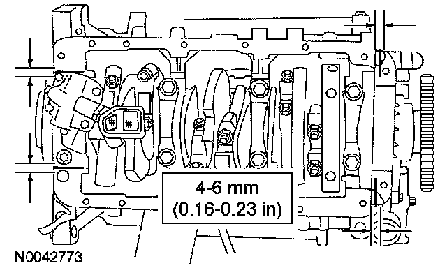
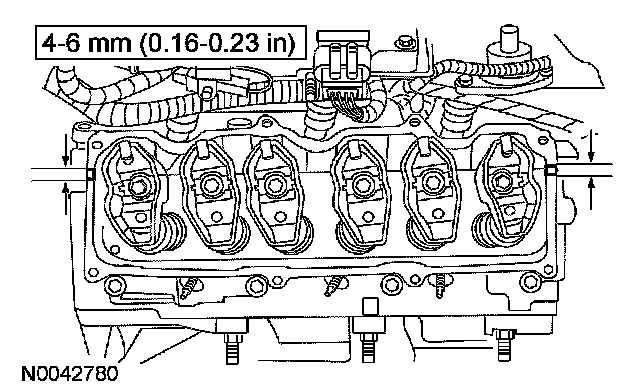
CAUTION: The thickness of the sealant must be between 4-6 mm (0.16-0.23 inch) or oil leaks could occur.
NOTE: If not secured within 4 minutes, the sealant must be removed and the sealing area cleaned. To clean the sealing area, use silicone gasket remover and metal surface prep. Observe all warnings and cautions and follow all application directions contained on the packaging of the silicone gasket remover and metal surface prep. Allow to dry until there is no sign of wetness, or 4 minutes, whichever is longer. Failure to follow this procedure can cause future oil leakage.
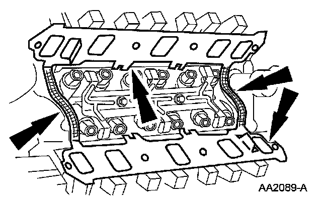
Apply a 4.0 - 6.0 mm (0.16 - 0.23 inch) bead of silicone gasket and sealant to the junction of the rear main bearing cap and the cylinder block, and to the junction of the front cover assembly and cylinder block.
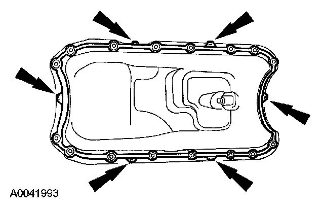
37. Position a new oil pan gasket to the oil pan by aligning the fastener holes and securing the gasket with the gasket clips.
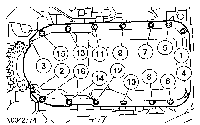
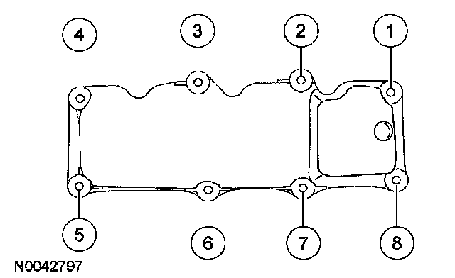
38. NOTE: Make sure the fasteners are clean and dry prior to installation.
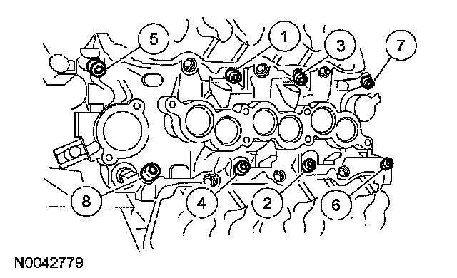
Install the oil pan and bolts. Tighten in the sequence shown.
^ Tighten to 12 Nm (9 ft. lbs.).
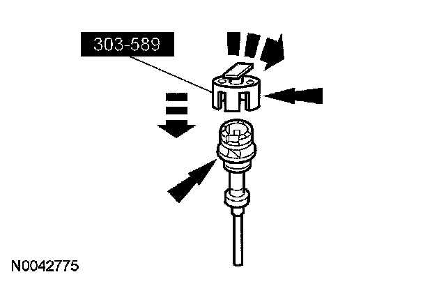
39. CAUTION: A synchronizer alignment gauge must be used during the installation of the synchronizer assembly. Failure to follow this procedure will result in the fuel system being out of time with the engine, possibly causing engine damage.
CAUTION: After installation, do not loosen the synchronizer bolt and rotate the synchronizer assembly. The synchronizer assembly is not adjustable. Do not loosen the synchronizer bolt after the alignment tool has been removed in order to align the CMP electrical connector for any reason. If the electrical connector is not in the correct position, the synchronizer assembly must be removed, the alignment tool and the assembly reinstalled if the engine has not been rotated from TDC of the compression stroke on the No. 1 cylinder.
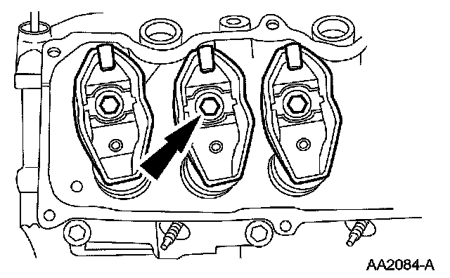
Install the special tool on the camshaft synchronizer by rotating the tool until it engages the notch in the camshaft synchronizer housing.
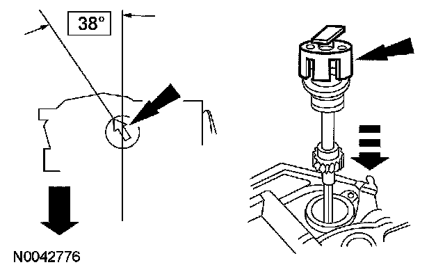
40. NOTE: Always coat the synchronizer drive gear with clean engine oil prior to installation.
NOTE: During installation, the arrow on the special tool will rotate clockwise as the gears engage.
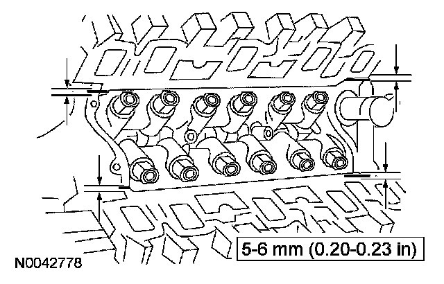
Install the camshaft synchronizer housing assembly so the arrow on the synchronizer alignment gauge is 38 degrees from the centerline of the engine.
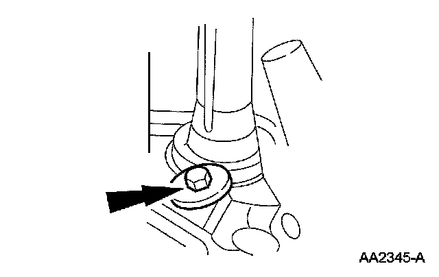
41. Install the camshaft synchronizer retaining bolt.
^ Tighten to 30 Nm (22 ft. lbs.).
42. Install the camshaft position (CMP) sensor.
^ Tighten to 3 Nm (27 inch lbs.).
43. CAUTION: Do not use metal scrapers, wire brushes, power abrasive discs or other abrasive means to clean the sealing surfaces. These tools cause scratches and gouges, which make leak paths. Use a plastic scraping tool to remove all traces of old sealant.
NOTE: If not secured within 4 minutes, the sealant must be removed and the sealing area cleaned. To clean the sealing area, use silicone gasket remover and metal surface prep. Observe all warnings and cautions and follow all application directions contained on the packaging of the silicone gasket remover and metal surface prep. Allow to dry until there is no sign of wetness, or 4 minutes, whichever is longer. Failure to follow this procedure can cause future oil leakage.
Apply 4 beads of silicone gasket and sealant.
44. Install new intake manifold gaskets and end seals.
^ Position the intake manifold gaskets.
^ Position the end seals.
45. Install the lower intake manifold and bolts. Tighten in sequence shown.
^ Tighten to 29 Nm (21 ft. lbs.).
46. Install the push rods and the rocker arms.
^ Install the push rods.
^ Install the rocker arms and bolts.
^ Tighten to 32 Nm (24 ft. lbs.).
47. CAUTION: Do not use metal scrapers, wire brushes, power abrasive discs or other abrasive means to clean the sealing surfaces. These tools cause scratches and gouges, which make leak paths. Use a plastic scraping tool to remove all traces of old sealant.
NOTE: Clean the valve cover gasket sealing surface with silicone gasket remover and metal surface prep. Observe all warnings and cautions and follow all application directions contained on the packaging of the silicone gasket remover and metal surface prep.
Apply a bead of silicone gasket and sealant to the 4 intake-to-cylinder head seams.
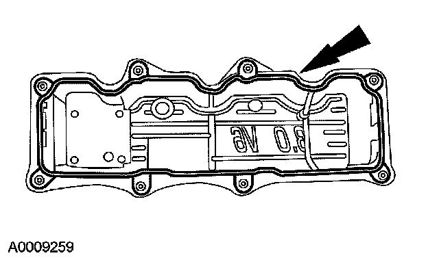
48. Install new valve cover gaskets.
49. Install the valve covers and bolts. Tighten in the sequence shown.
^ Tighten to 12 Nm (9 ft. lbs.).
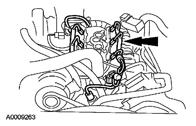
50. Position the engine control sensor wiring and connect:
^ the CMP sensor.
^ the fuel injectors.
^ the water temperature indicator sender unit.
^ the engine control sensor wiring.
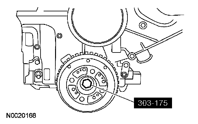
51. Using the special tool, install the crankshaft damper.
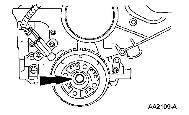
52. Install the bolt.
^ Tighten to 145 Nm (107 ft. lbs.).
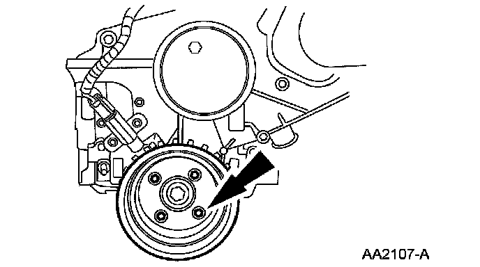
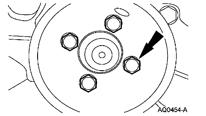
53. Install the crankshaft pulley and the 4 bolts.
^ Tighten to 63 Nm (46 ft. lbs.).
54. Install the coolant pump pulley and the 4 bolts.
^ Tighten to 25 Nm (18 ft. lbs.).
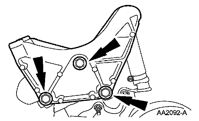
55. Install the generator mounting bracket and the bolts.
^ Tighten to 47 Nm (35 ft. lbs.).
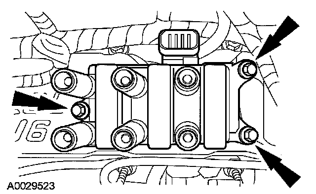
56. Position the ignition coil assembly and install the bolts.
^ Tighten to 6 Nm (53 inch lbs.).
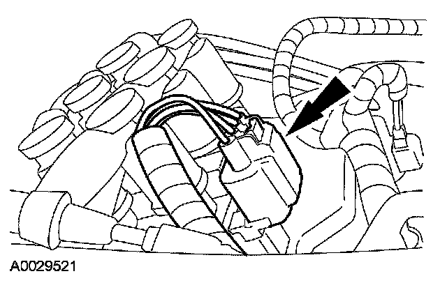
57. Connect the ignition coil.
58. Connect the spark plug wires. For additional information, refer to Ignition System.
59. Install the Lifting Eyes and the lifting equipment.
60. Remove the engine from work stand.
61. Install the engine-to-transmission spacer plate.
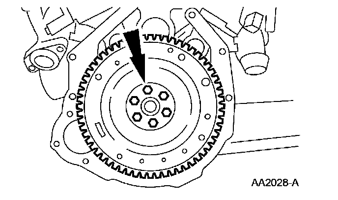
62. Install the flywheel or flexplate.
^ Tighten to 80 Nm (59 ft. lbs.).
Vehicles equipped with a manual transmission
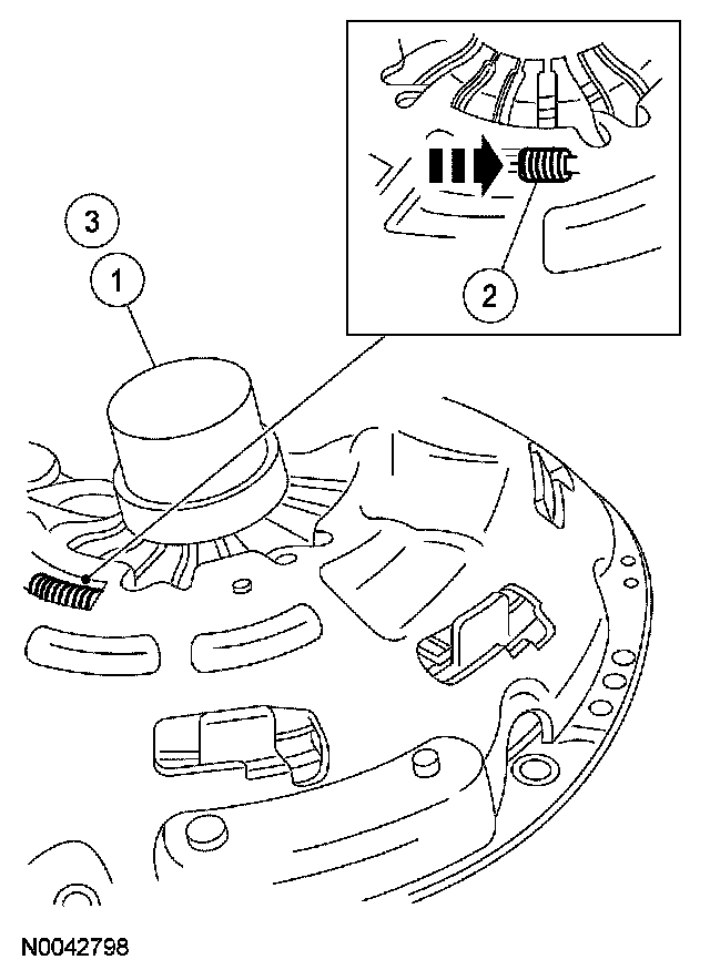
63. Adjust the clutch pressure plate.
1. Using a suitable press, press downward on the fingers until the adjusting ring moves freely.
2. Rotate the adjusting ring counterclockwise to compress the tension springs. Hold the adjusting ring in this position.
3. Release the pressure on the fingers. The adjusting ring will stay in the reset position.
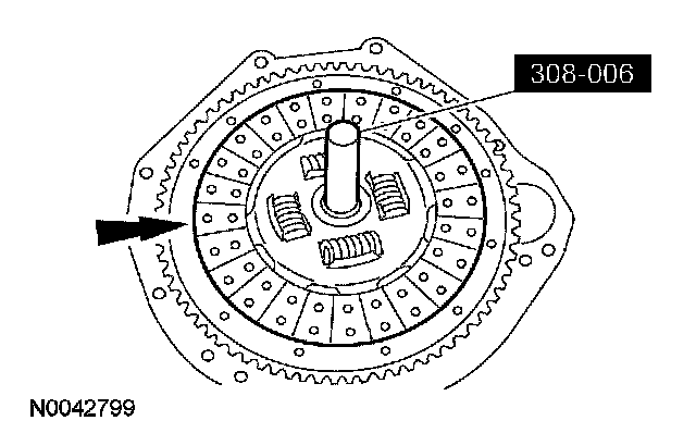
64. Using the special tool, position the clutch disc on the flywheel.
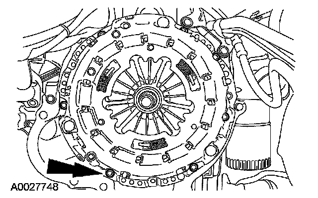
65. NOTE: If reusing the clutch pressure plate and flywheel, align the marks made during removal.
Position the clutch pressure plate and install the bolts. Tighten the bolts in a star pattern.
^ Tighten to 32 Nm (24 ft. lbs.).