Part 1
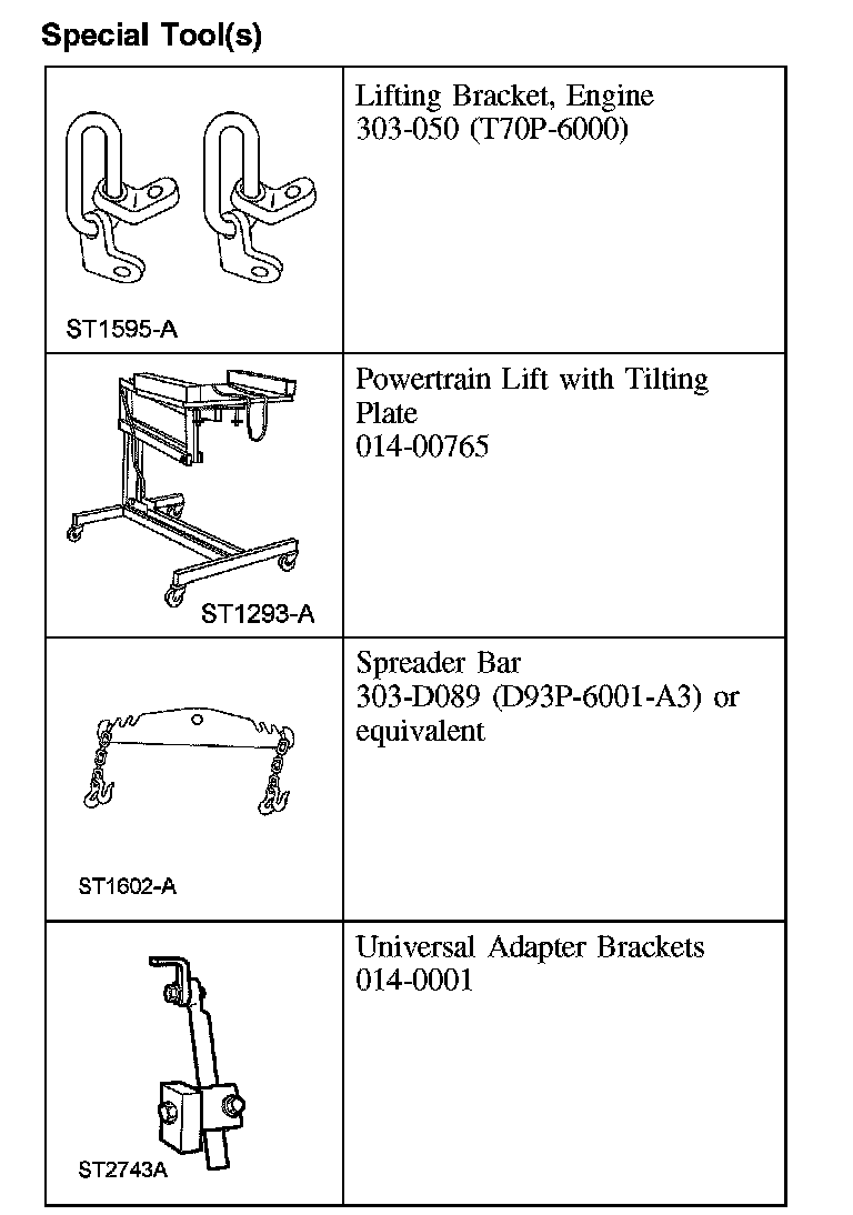
EngineSpecial Tool(s):
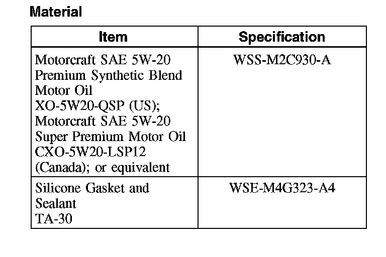
Material:
Installation (Steps 1-33)
CAUTION: If the oil pan was removed during engine disassembly, it must be installed after the engine and transaxle are assembled and the transaxle-to-engine bolts are installed. Failure to follow this assembly sequence can result in engine oil leaks.
All vehicles
1. Using the special tools, align the engine with the transaxle.
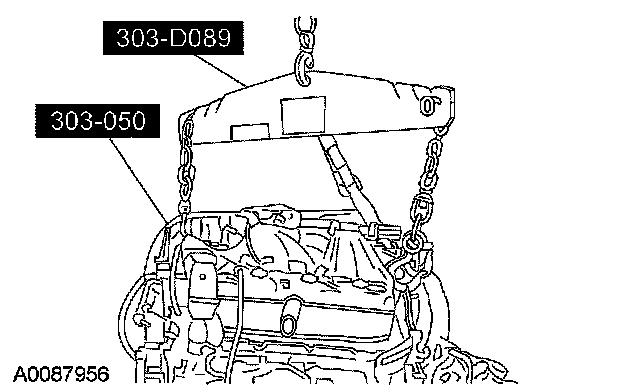
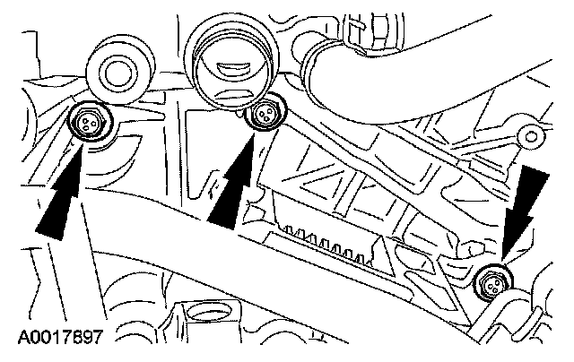
2. Install the 7 transaxle bolts.
^ Tighten to 40 Nm (30 ft. lbs.)
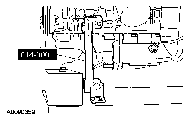
3. Using the special tools, secure the engine to the powertrain lift.
All wheel drive (AWD) vehicles
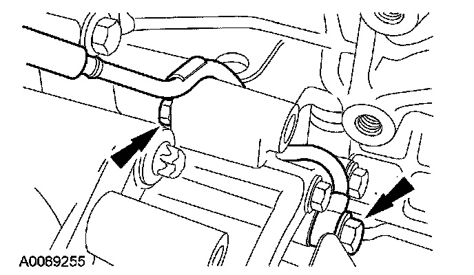
4. Position the power take off, attach the pin-type retainer and install the bolt.
^ Tighten to 14 Nm (10 ft. lbs.)
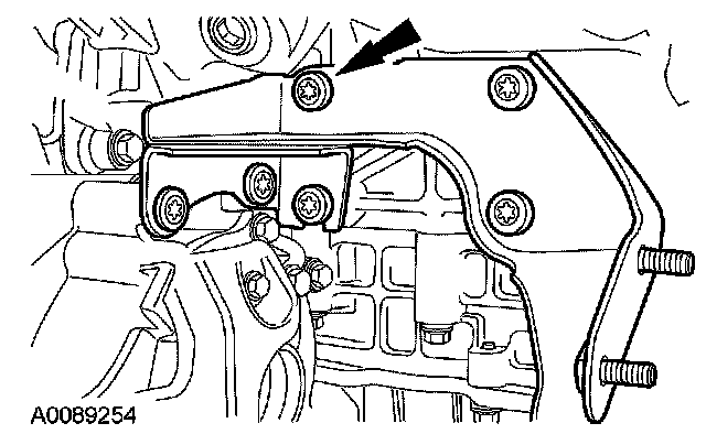
5. Install the halfshaft support bracket and the bolts.
^ Tighten to 48 Nm (35 ft. lbs.)
6. Install 6 new RH exhaust manifold studs.
^ Tighten to 12 Nm (9 ft. lbs.)
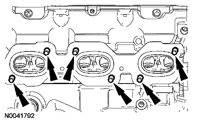
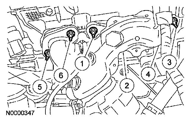
7. Install a new gasket and the RH exhaust manifold and new nuts.
^ Tighten in the sequence shown to 20 Nm (15 ft. lbs.)
All vehicles
8. Connect the turbine speed sensor (TSS) electrical connector.
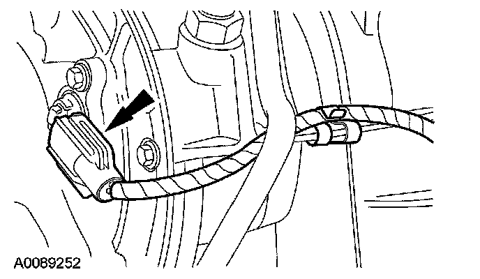
9. Attach the transaxle control harness to the brackets.

10. Connect the transaxle wiring harness electronic control switch electrical connector.
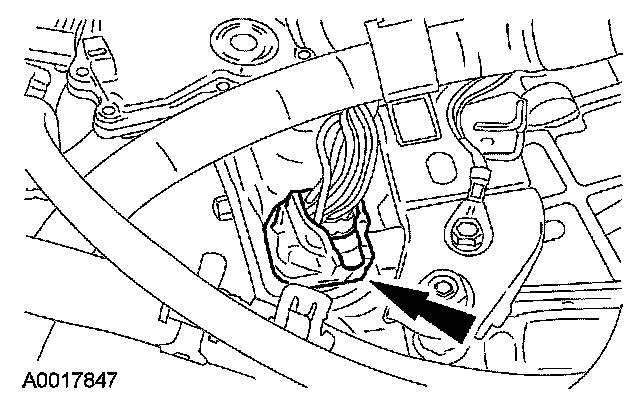
11. Connect the transmission range (TR) sensor electrical connector.
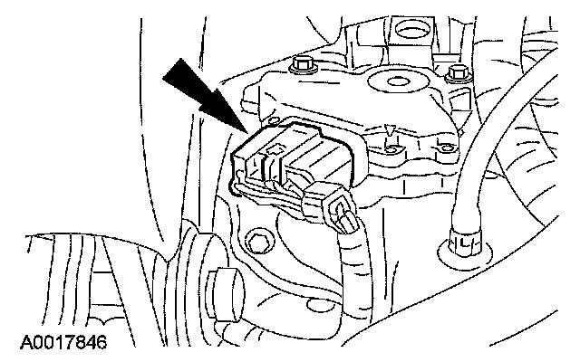
12. Attach the pin-type retainers to the transaxle support bracket and connect the heated oxygen sensor (HO2S) and catalyst monitor sensor electrical connectors.
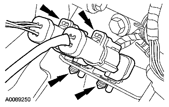
13. Position the powertrain into the vehicle.
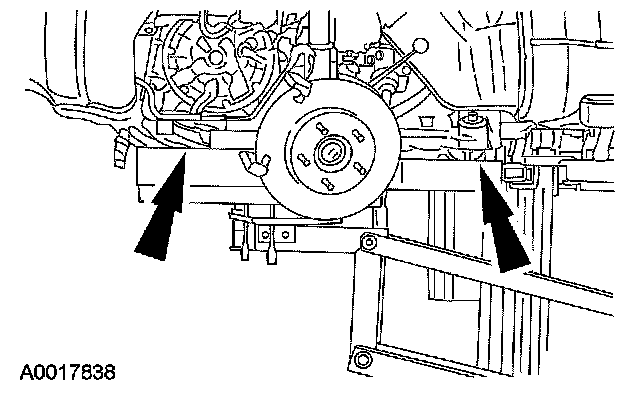
14. Install the front engine support nuts.
^ Tighten to 55 Nm (41 ft. lbs.)
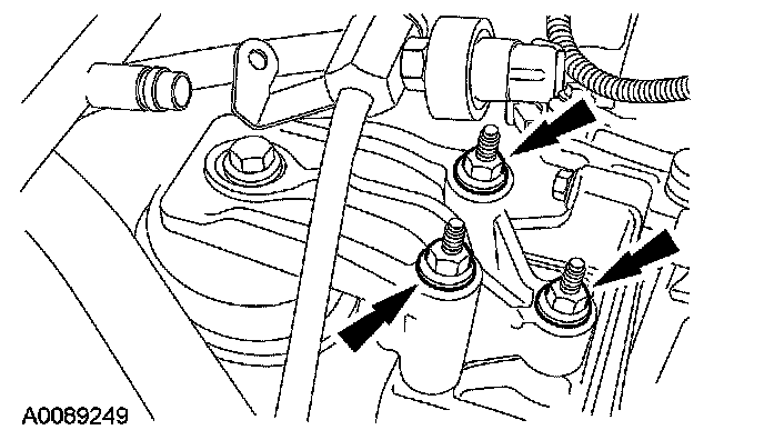
15. Install the rear transaxle support bolt.
^ Tighten to 103 Nm (76 ft. lbs.)
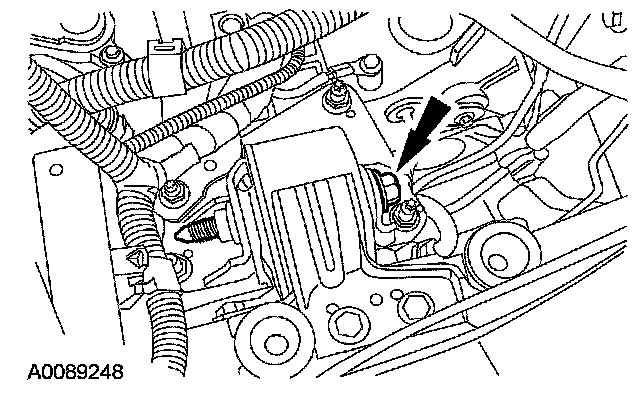
16. Position the RH transaxle support insulator and install the bolt and nuts.
^ Tighten to 80 Nm (59 ft. lbs.)
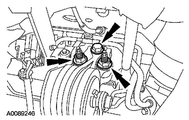
17. Install the RH transaxle support insulator bolt.
^ Tighten to 115 Nm (85 ft. lbs.)
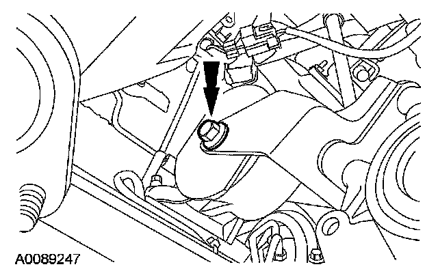
18. NOTE: Clean and degrease all sealing surfaces with metal surface cleaner.
NOTE: The oil pan must be installed and the bolts tightened within 4 minutes of the sealant application.
Apply a 10 mm (0.39 inch) dot of silicone gasket and sealant to the front cover-to-cylinder block sealing surface.
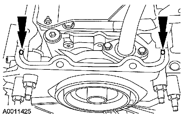
19. NOTE: Install a new oil pan gasket.
Position the oil pan and gasket and loosely install the bolts and stud bolts.
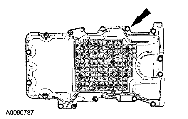
20. Install the 2 oil pan-to-transaxle bolts.
^ Tighten to 40 Nm (30 ft. lbs.)
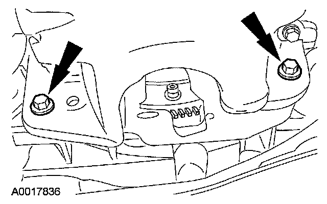
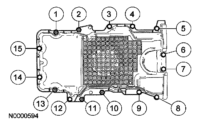
21. Tighten the oil pan bolts in the sequence shown to 25 Nm (18 ft. lbs.)
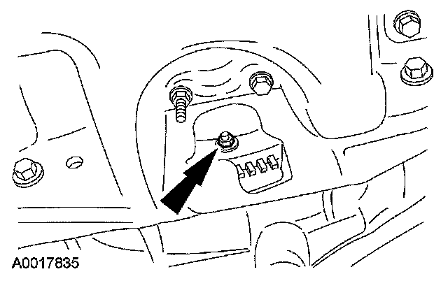
22. Install the 4 torque converter nuts.
^ Tighten to 40 Nm (30 ft. lbs.)
23. Install the torque converter inspection cover.
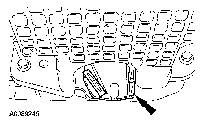
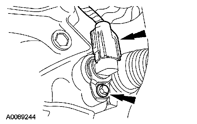
24. Install the output shaft speed (OSS) sensor and the bolt and connect the electrical connector.
^ Tighten to 13 Nm (10 ft. lbs.)
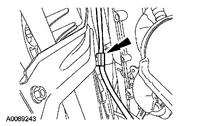
25. Attach the HO2S wiring retainer to the radiator center support.
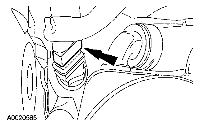
26. If equipped, connect the engine block heater electrical connector.
27. Attach the wiring harness retainers from the battery tray bracket.
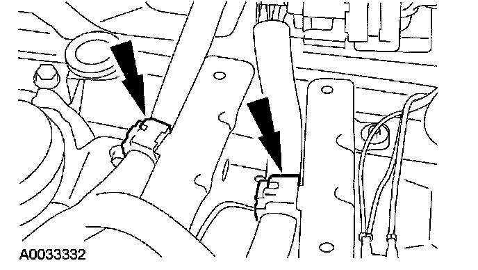
28. Position the ground strap and the electrical connector and install the bolts.
^ Tighten to 10 Nm (89 inch lbs.)
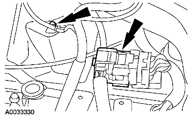
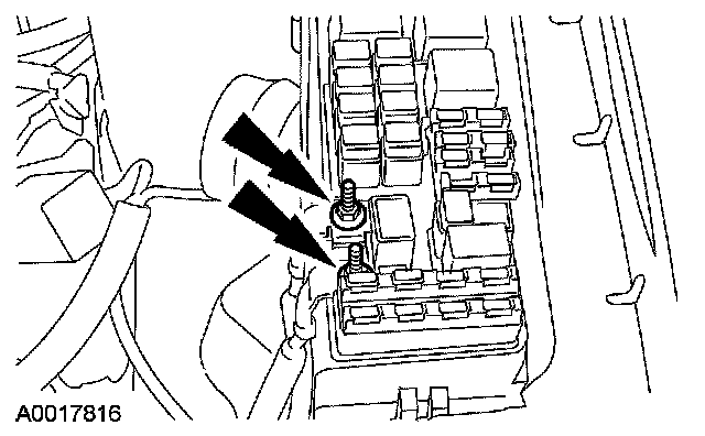
29. Install the cables and the nuts.
^ Tighten to 12 Nm (9 ft. lbs.)
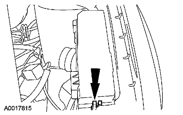
30. Install the power distribution box cover.
31. Attach the ground wire and install the bolt.
^ Tighten to 10 Nm (89 inch lbs.)
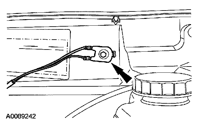
32. Position the wiring and install the nut. Connect the powertrain control module (PCM) electrical connectors.
^ Tighten to 8 Nm (71 inch lbs.)
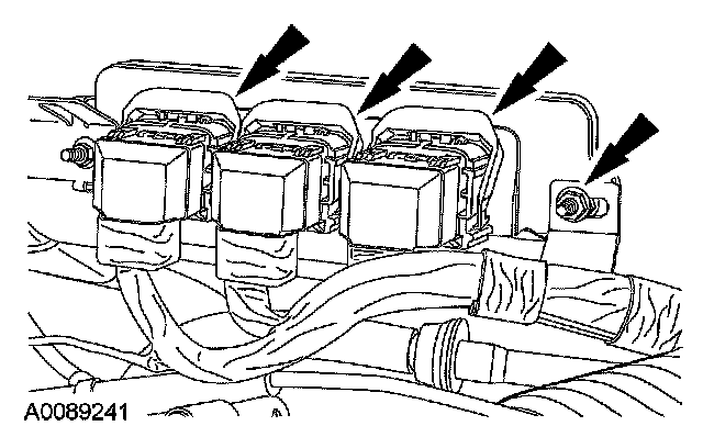
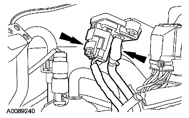
33. Connect the manifold absolute pressure (MAP) sensor electrical connector and vacuum tube.