Occupant Classification Sensor - Service Kit
OCCUPANT CLASSIFICATION SENSOR - SERVICE KITSpecial Tool(s):
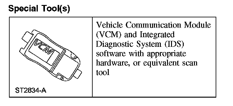
Special Tool(s)
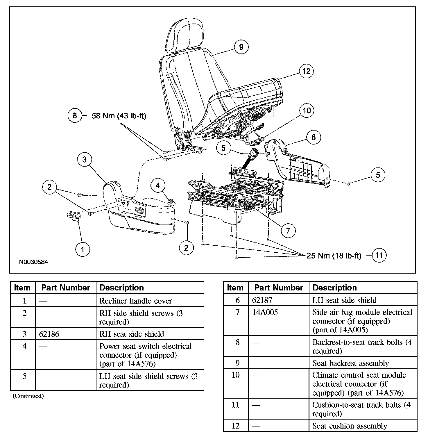
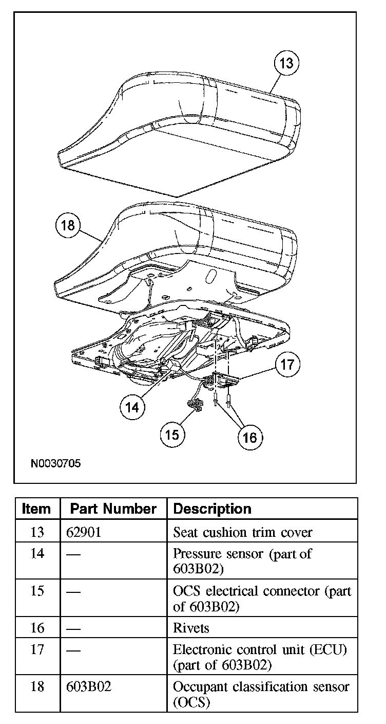
Removal
WARNING:
- Always wear safety glasses when repairing an air bag supplemental restraint system (SRS) vehicle and when handling an air bag module. This will reduce the risk of injury in the event of an accidental deployment.
- Never probe the connectors on the air bag module. Doing so can result in air bag deployment, which can result in personal injury.
- The safety belt pretensioner is a pyrotechnic device. Always wear safety glasses when repairing an air bag equipped vehicle and when handling a safety belt buckle pretensioner or safety belt retractor pretensioner. Never probe a pretensioner electrical connector. Doing so could result in pretensioner or air bag deployment and could result in personal injury.
- To reduce the risk of personal injury, do not use any memory saver devices.
CAUTION:
- There are 3 occupant classification sensor (OCS) system service kits available for this vehicle (base seat, heated seat and climate controlled seat). Always make sure the correct OCS service kit is installed.
- It is necessary to carry out the OCS system reset when a front passenger seat cushion is disassembled, a new trim cover installed, a seat side shield removed, or an OCS service kit is installed. A scan tool is used to trigger the active command to carry out the OCS system reset.
NOTE:
- If a seat equipped with a supplemental restraint system (SRS) component is being serviced, the SRS must be depowered.
- The air bag warning lamp illuminates when the restraints control module (RCM) fuse is removed and the ignition switch is ON. This is normal operation and does not indicate a supplemental restraint system (SRS) fault.
- The heated seat element on the front passenger seat cushion is not serviceable separately. If a new heated seat element is needed on the front passenger seat cushion a new occupant classification sensor (OCS) service kit, equipped with a heated seat element, must be installed.
- Occupant classification sensor (OCS) system components (seat cushion foam pad, bladder with pressure sensor and electronic control unit) are calibrated to each other and are serviced as an assembly. The OCS system components are not to be installed separately. If a new OCS system, OCS system component or seat cushion foam pad are needed, a new OCS system service kit (seat cushion foam pad, bladder with pressure sensor and electronic control unit) must be installed as an assembly.
- To identify between a production OCS system and a service OCS system (OCS service kit) inspect the electronic control unit (ECU) electrical connector. A production OCS system allows the disconnect of the ECU electrical connector. A service OCS system (OCS service kit) has the ECU electrical connector glued to the ECU, it cannot and should not be disconnected or altered.
- The SRS must be fully operational and free of faults before releasing the vehicle to the customer.
- Repair is made only by installing a new assembly. If the new assembly does not correct the condition, install the original equipment and carry out the diagnostic procedure again.
Manual seats
1. Depower the supplemental restraint system (SRS).
Power seats
2. Remove the passenger seat and depower the system.
3. Release the recliner handle cover tab and remove the cover.
4. Remove the 3 screws and the RH side shield.
5. Disconnect the power seat switch electrical connector.
6. Remove the 3 screws and the LH side shield.
Seats with side air bags
7. Separate the side air bag module electrical connector and wire harness pin-type retainers from the seat riser and cushion pan.
8. Disconnect the seat side air bag module electrical connector.
Power seats
9. Detach the seat cushion rear trim cover J-clip.
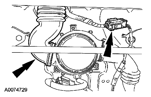
10. Separate the climate control duct and disconnect the backrest thermal electric device electrical connector (if equipped).
11. Disconnect the 2 backrest heated seat element electrical connectors (if equipped).
12. Remove the 4 backrest-to-seat track bolts.
13. Remove the seat backrest assembly.
- If equipped, remove the seat backrest assembly while feeding the climate control seat duct and wiring out through the seat cushion trim cover.
All seats
14. Disconnect and release any remaining electrical connectors and pin-type retainers necessary to remove the seat cushion pan from the seat track (if equipped).
15. Remove the 4 cushion-to-seat track bolts.
16. Remove the seat cushion assembly.
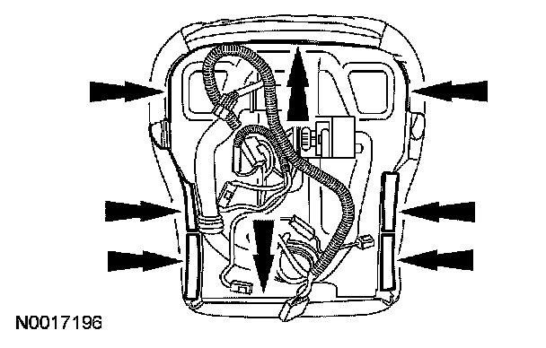
17. Release the seat cushion trim cover J-clips from the seat cushion pan.
- If equipped, disconnect the seat cushion heated seat element electrical connector.
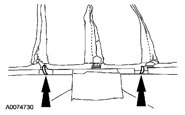
18. CAUTION: Use care when separating the seat upholstery from the hook and loop strip, or the hook and loop strip can be torn from the seat cushion foam pad.
If installing a new OCS service kit or installing a new seat cushion trim cover, remove the hog rings and separate the trim cover from the foam pad.
- After removing the hog rings, place a hand between the trim cover and foam pad and carefully separate the hook and loop strips.
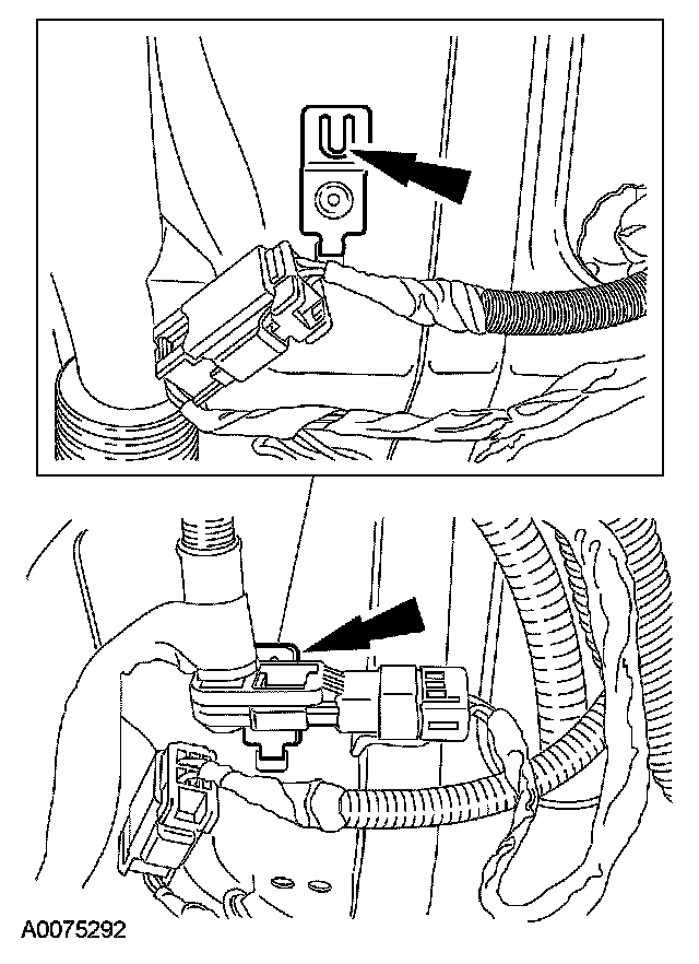
19. NOTE: The OCS service kit connector connects to the seat wiring harness.
Disconnect the OCS service kit connector and remove any retainers from their wiring harness.
20. CAUTION: Care must be taken to prevent damage to the seat cushion pan when removing the rivets.
Remove the 2 OCS electronic control unit (ECU) rivets.
21. Remove the OCS ECU from the bracket.
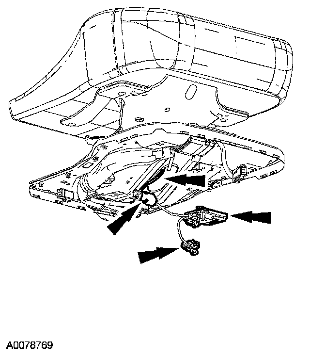
22. Remove the OCS.
- Feed the OCS components (hose, transducer, wire harness, ECU and connectors) through the seat cushion pan opening and remove as an assembly with the bladder.
Installation
NOTE: If installing an OCS service kit, refer to Occupant Classification Sensor - Service Kit.
All seats
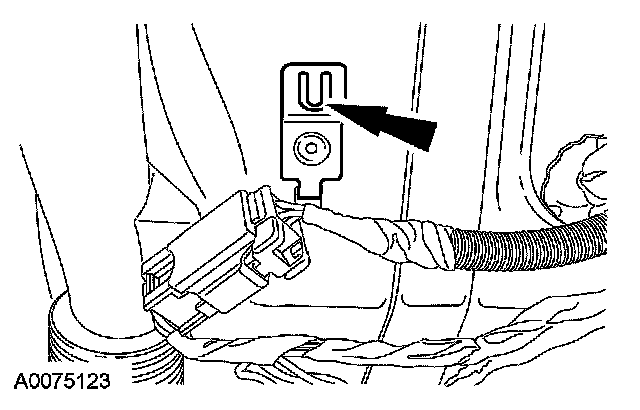
1. Bend the retaining tab back on the pressure sensor component bracket.
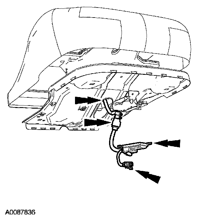
2. CAUTION:
- Inspect the seat cushion foam pad and pan for any foreign material before installing the seat cushion foam pad to the seat cushion pan. If any foreign material is found, remove it. Failure to do so may result in personal injury, in the event of an air bag deployment.
- Failure to route the seat occupant classification sensor components through the correct seat cushion support opening can cause safety system failure.
- While positioning the seat cushion pan and occupant classification sensor assembly, be careful not to damage any of the components. Failure to do so can result in component failure.
Feed the OCS service kit components (hose, pressure sensor, ECU, wire harness and connectors) through the seat cushion pan opening.
3. CAUTION: Inspect the seat cushion foam pad and pan for any foreign material before installing the seat cushion foam pad to the seat cushion pan. If any foreign material is found, remove it. Failure to do so may result in personal injury, in the event of an air bag deployment.
Using hog rings, attach the seat cushion trim cover to the seat cushion foam pad.
4. Position the seat cushion foam pad with the OCS bladder to the seat cushion pan and set in place.
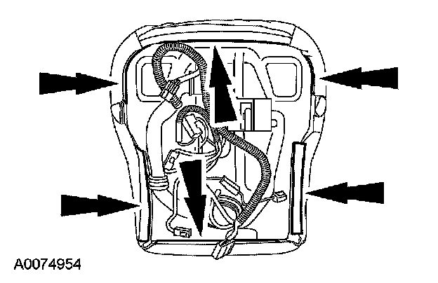
5. CAUTION: Inspect the seat cushion foam pad and seat cushion trim cover for any foreign material, before installing the seat cushion trim cover to the seat cushion foam pad. If any foreign material is found, remove it. Failure to do so may result in personal injury, in the event of an air bag deployment.
Attach the seat cushion trim cover J-clips to the seat cushion pan.
Power seats
6. Connect the heated seat cushion electrical connector (if equipped).
All seats
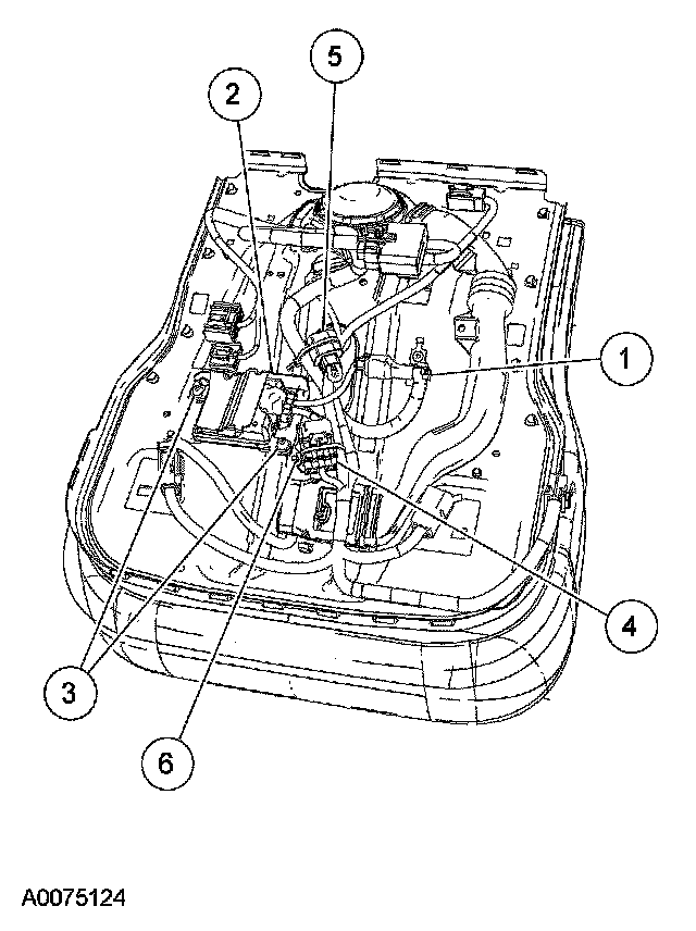
7. NOTE:
- When installing an occupant classification sensor service kit, the seat wire harness pressure sensor electrical connector is not used.
- Make sure the pressure sensor hose is not kinked during installation.
Install the OCS components to the seat cushion pan.
1 Install the pressure sensor onto the seat cushion pan bracket, making sure the retaining tab is completely engaged.
- When installed correctly, an audible click will be heard and the pressure sensor will not be able to be removed from its bracket without disengaging the retaining tab.
2 Slide the ECU into the seat cushion pan bracket.
- The ECU must be correctly positioned and securely fastened in place. Failure to do so can set a diagnostic trouble code (DTC) in the RCM.
3 Install the rivets.
4 Connect the main seat wire harness occupant classification sensor electrical connector.
5 Tie-strap the unused main seat wire harness pressure sensor electrical connector safely aside.
6 Tie-strap all loose wire harnesses and electrical connectors aside.
8. CAUTION: While positioning the seat cushion pan and occupant classification sensor assembly, be careful not to damage any of the components. Failure to do so can result in component failure.
Position the seat cushion and pan assembly to the seat track.
9. Install the 4 cushion pan-to-seat track bolts.
- Tighten to 25 Nm (18 lb-ft).
10. Install all wire harnesses and connect all electrical connectors to the seat pan (if equipped).
Power seats
11. Install the backrest assembly.
- If equipped, install the seat backrest assembly while feeding the climate control seat duct and wiring in through the seat cushion trim cover.
12. Install the 4 backrest-to-seat track bolts.
- Tighten to 58 Nm (43 lb-ft).
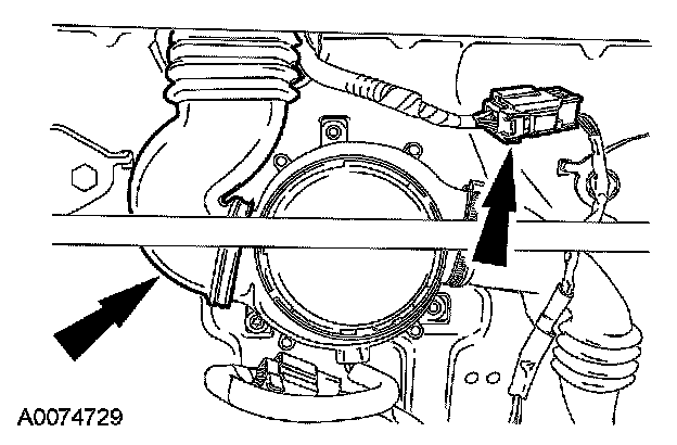
13. Connect the climate control duct and the backrest thermal electrical device electrical connector (if equipped).
14. Connect the 2 seat backrest heated seat element electrical connectors (if equipped).
15. Attach the seat cushion rear trim cover J-clip.
Seats with side air bags
16. Route the air bag module wire harness and electrical connector and attach to the seat riser and cushion pan.
17. Connect the seat side air bag module electrical connector.
Power seats
18. Install the LH side shield and 3 screws.
19. Connect the power seat switch electrical connector.
20. Install the RH side shield and 3 screws.
21. Install the recliner handle.
22. Install the passenger seat and repower the system. Do not prove out the system at this time.
- Make sure the safety belts and buckles are accessible to the occupants after installation.
Manual seats
23. Repower the SRS. Do not prove out the system at this time.
- Make sure the safety belts and buckles are accessible to the occupants after installation.
All seats
24. WARNING: Do not separate components.
CAUTION:
- It is necessary to carry out the OCS system reset when a front passenger seat cushion is disassembled, a new trim cover installed, a seat side shield removed, or an OCS service kit is installed. A scan tool is used to trigger the active command to carry out the OCS system reset.
- Make sure the seat is completely assembled before carrying out the OCS system reset.
- The following precautions must be taken before carrying out the OCS system reset:
- Make sure the OCS system components are connected and no faults are present.
- Make sure the OCS system is not at a temperature below 0°C (32°F) or above 45°C (113°F) when initiating the OCS system reset process. If the vehicle has been exposed to extreme cold or hot temperatures, the vehicle must be exposed and kept at a temperature within the limits, 0°C to 45°C (32°F to 113°F) for a minimum of 30 minutes.
- Make sure nothing is present on the passenger seat before carrying out the OCS system reset and nothing is placed on the seat during the OCS system reset process.
- Make sure a minimum 8-second time period has passed after cycling the ignition switch ON before the process.
NOTE:
- For best results, the OCS system should be at or near room temperature, 10°C to 29°C (50°F to 85°F).
- If the first attempt to carry out the OCS system reset is unsuccessful, a second attempt must be made.
Carry out the OCS system reset active command using the scan tool.
- With the front passenger seat empty, use a scan tool to trigger the active command.
25. NOTE: The ignition switch must be cycled after carrying out the OCS system reset.
Cycle the ignition switch from ON to OFF.
26. Prove out the supplemental restraint system (SRS) as follows:
Turn the ignition key from ON to OFF. Wait 10 seconds, then turn the key back to ON and visually monitor the air bag indicator with the air bag modules installed. The air bag indicator will light continuously for approximately 6 seconds and then turn off. If an air bag supplemental restraint system (SRS) fault is present, the air bag indicator will:
- fail to light.
- remain lit continuously.
- flash.
The flashing might not occur until approximately 30 seconds after the ignition switch has been turned from the OFF to the ON position. This is the time required for the RCM to complete the testing of the SRS. If the air bag indicator is inoperative and a SRS fault exists, a chime will sound in a pattern of 5 sets of 5 beeps. If this occurs, the air bag indicator and any SRS fault discovered must be diagnosed and repaired.
Clear all continuous DTCs from the restraints control module using a scan tool.
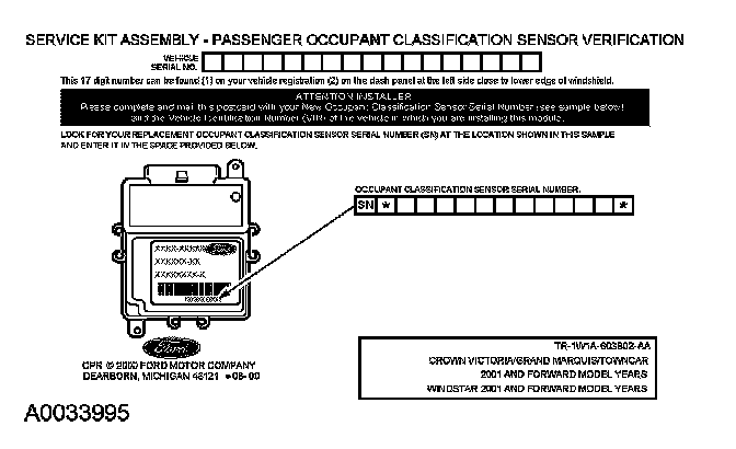
27. NOTE: When installing a new occupant classification sensor, a prepaid return postcard is provided with the new occupant classification sensor. The serial number for the new part and the vehicle identification number (VIN) must be recorded and sent to Ford Motor Company.
Fill out the necessary information on the occupant classification sensor traceability card and return it along with the complete inoperative occupant classification sensor to Ford Motor Company.
- When returning the inoperative occupant classification sensor, include the following seat cushion foam pad, bladder, electronic control unit, pressure sensor (transducer), hose, electrical connectors and wire harness (service part occupant classification sensor only).